Radiofrequency wave transmission circuit using arbitrary waveform generator and NMR apparatus using the same

a radiofrequency wave and generator technology, applied in the direction of using reradiation, instruments, diagnostic recording/measuring, etc., can solve the problems of inability to comprehend whether a pulse waveform practically prepared by a user runs well or not, and the degree of freedom of designing the radiofrequency wave transmission pulse for the nmr apparatus can be drastically improved

Inactive Publication Date: 2006-11-07
HITACHI LTD
View PDF8 Cites 2 Cited by
  • Summary
  • Abstract
  • Description
  • Claims
  • Application Information

AI Technical Summary

Benefits of technology

[0005]As the technological development of magnets advances and the intensity of a magnetic field of an NMR measuring apparatus increases, there results an advantage that confers improved sensitivity upon the user. With the magnetic field intensity increased, necessary power of the radiofrequency pulse so increases as to excessively increase energy applied to the sample, resulting in a problem that the temperature of the sample is raised.
[0010]An object of this invention is to further increase the degree of freedom of selective excitation. If the user can afford to freely program selective excitation frequencies, an excitation pulse most suited for a sample to be measured can be set freely. As a result, the temperature of the sample can be prevented from rising and spectra can be fetched efficiently. Also, an efficient excitation pulse matching a spectral pattern radiating from the sample can be designed freely.
[0012]According to the present invention, the degree of freedom of designing the radiofrequency wave transmission pulse for the NMR apparatus can be improved drastically.

Problems solved by technology

With the magnetic field intensity increased, necessary power of the radiofrequency pulse so increases as to excessively increase energy applied to the sample, resulting in a problem that the temperature of the sample is raised.
Further, whether a program of a pulse waveform practically prepared by a user runs well or not cannot be comprehended in many cases unless simulation is carried out by solving the Bloch equation.

Method used


Image

  • Radiofrequency wave transmission circuit using arbitrary waveform generator and NMR apparatus using the same
  • Radiofrequency wave transmission circuit using arbitrary waveform generator and NMR apparatus using the same
  • Radiofrequency wave transmission circuit using arbitrary waveform generator and NMR apparatus using the same

Examples


Embodiment Construction

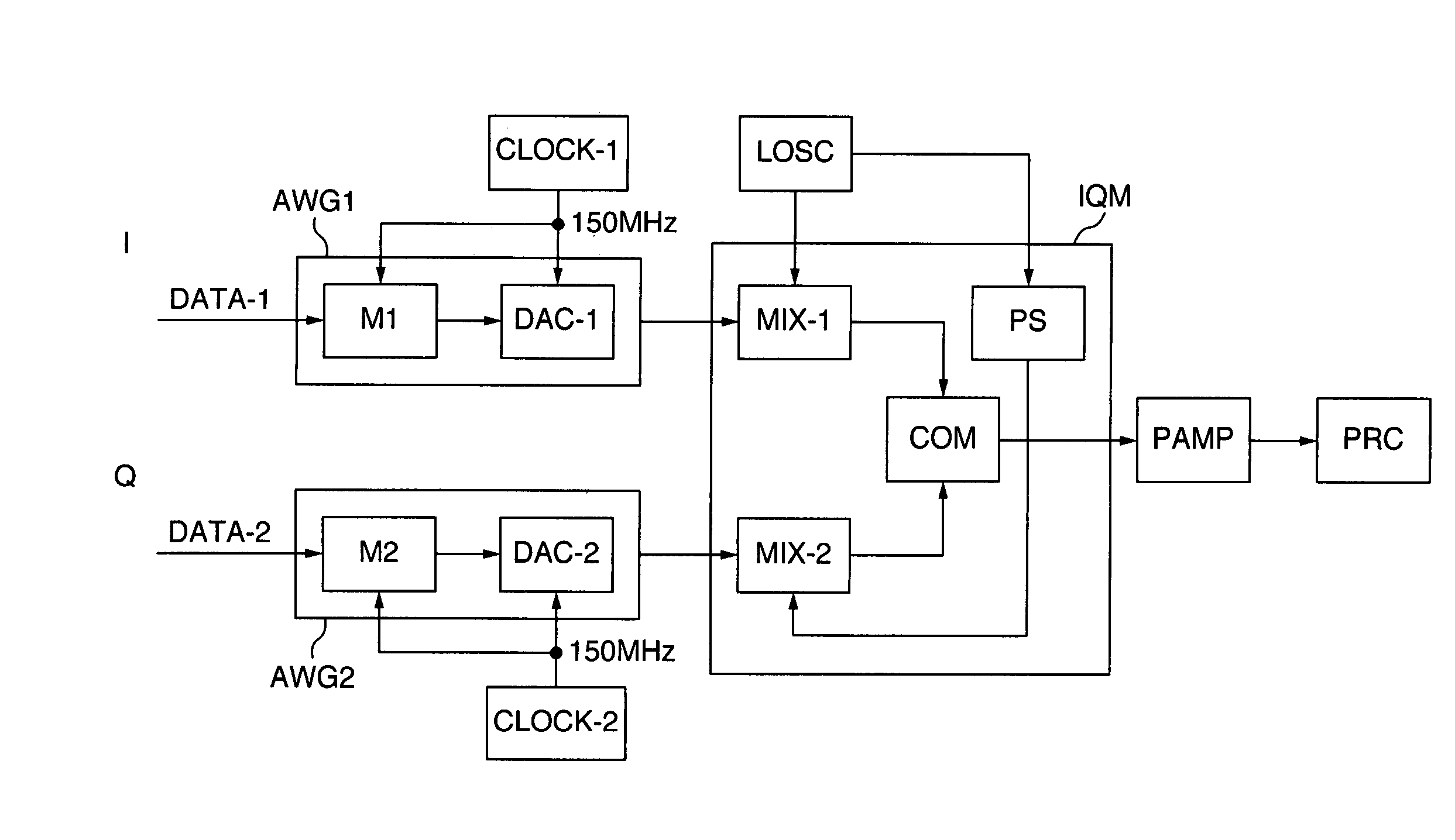
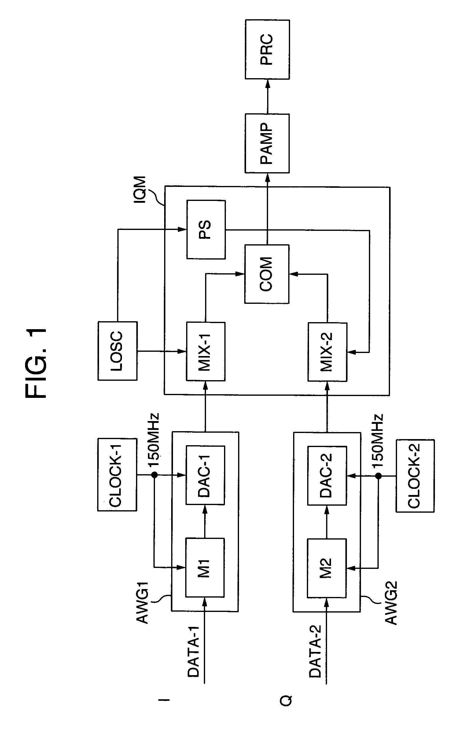
[0020]Referring now to FIG. 1, there is illustrated, in block diagram form, an embodiment of this invention. The data of DATA-1 and DATA-2 generated by using a computer, for instance, are inputted to two arbitrary waveform generators AWG1 and AWG2, respectively, and are once stored in memories M1 and M2. For example, these data are stored in synchronism with reference clocks CLOCK-1 and CLOCK-2 of about 150 MHz.

[0021]The stored data are subjected to digital to analog conversion by means of digital to analog converters DAC-1 and DAC-2 and delivered in the form of electrical voltages. These output voltages are applied to an IQ modulator IQM. The maximum frequency generated by the arbitrary waveform generators AWG1 and AWG2 depend on the clock, amounting up to, for example, several MHz.

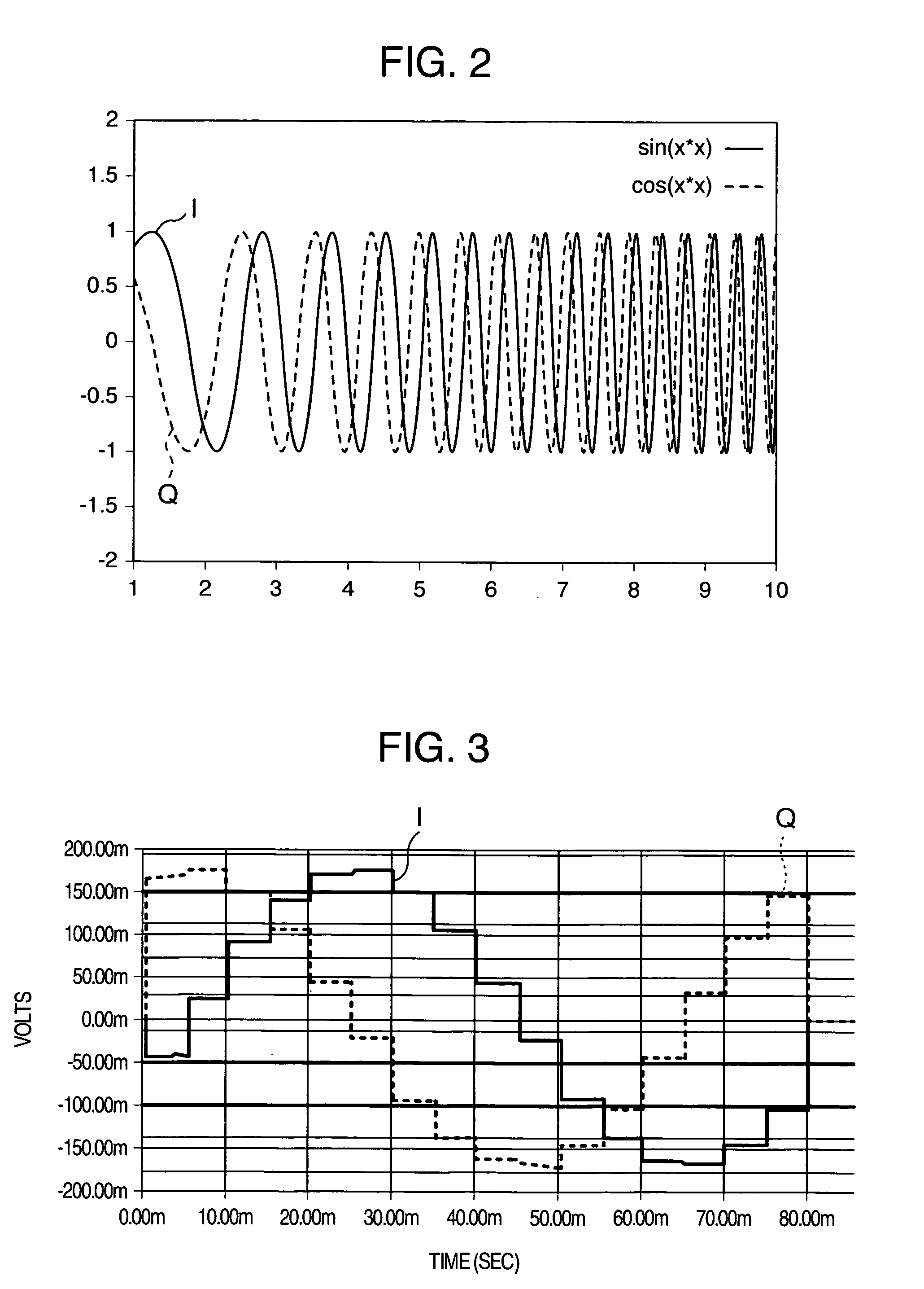
[0022]An example of the output waveforms of the two arbitrary waveform generators AWG1 and AWG2 are graphically depicted in FIG. 2. Waveforms I and Q represent the output waveforms of the arbitrary wavef...


PUM


Abstract

An NMR apparatus has a circuit adapted to improve the degree freedom of design and generate an excitation radiofrequency wave pulse suited for a sample to be measured. The radiofrequency wave transmission circuit includes a local oscillator, an IQ modulator having two mixers and two arbitrary waveform generators connected to the IQ modulator. Fourier inverse transform is applied to data inputted to the arbitrary waveform generators.

Description

BACKGROUND OF THE INVENTION[0001]The present invention relates to an NMR apparatus having a radiofrequency wave transmission circuit.[0002]Generally, in a nuclear magnetic resonance (hereinafter referred to as NMR) measuring apparatus, a radiofrequency wave is shaped into a pulse having a width of several microseconds and the pulse is irradiated on a sample, so that the level of a nuclear spin in the sample can be excited and a free induction decay signal from the nuclear spin can be received. Conventionally, when exciting the sample by selectively applying a frequency range to it, an excitation pulse is obtained by changing the phase and the amplitude of a pure sine wave independently of each other in a unit of several tens of nanoseconds.[0003]In the NMR measuring apparatus, excitation frequencies in a wide range spreading around a single frequency need to be generated. In this connection, a method called MREV or WALTZ for finely changing only the phase and a method such as E-BURP...

Claims


Application Information

Patent Timeline
Patent Type & Authority Patents(United States)
IPC IPC(8): G01V3/00A61B5/055G01R33/36
CPCG01R33/3607
Inventor HABARA, HIDETAPARK, MINSEOK
Owner HITACHI LTD
Why Eureka
Try Eureka