IR supercontinuum source

a supercontinuum source and source technology, applied in the field of optical supercontinuum generation, can solve the problems of increasing nonlinearities in fibers, limiting the transmission window in infrared, and the multiphonon edge of silica glass, so as to achieve the effect of reducing the bandwidth of ligh

Active Publication Date: 2006-11-07
THE UNITED STATES OF AMERICA AS REPRESENTED BY THE SECRETARY OF THE NAVY +2
View PDF9 Cites 27 Cited by
  • Summary
  • Abstract
  • Description
  • Claims
  • Application Information

AI Technical Summary

Benefits of technology

[0011]It is an object of this invention to broaden bandwidth of a light emanating from a chalcogenide solid core glass fiber.
[0012]It is another object of this invention to use a chalcogenide glass fiber that has sufficient optical transmission, sufficient nonlinearity, and proper dispersion to broaden spectral width of a light signal and thus make possible the achievement of high brightness infrared sources and the use of shorter length fiber.
[0013]It is another object of this invention to broaden spectral width of a coherent light source using a high nonlinearity chalcogenide glass fiber.
[0015]It is another object of this invention to use high nonlinearity chalcogenide glass fiber with smaller core sizes in fabrication of a photonic crystal fiber to allow for efficient supercontinuum generation using lower power pulse and continuous wave laser sources.

Problems solved by technology

In addition, very small core sizes are possible leading to high power densities and resulting in increased nonlinearities in the fiber.
In silica photonic crystal fiber, however, the multiphonon edge of silica glass limits the transmission window in the infrared.
This, in turn, limits the extent of spectral broadening in the infrared so that, to date, supercontinuum spectra have only been able to span from about 400 nm to about 2.2 μm.
Unfortunately, transmission limitations of the silica glass matrix of silica limits the supercontinuum generation to less than about 2 μm.

Method used


Image

  • IR supercontinuum source
  • IR supercontinuum source
  • IR supercontinuum source

Examples


example 1

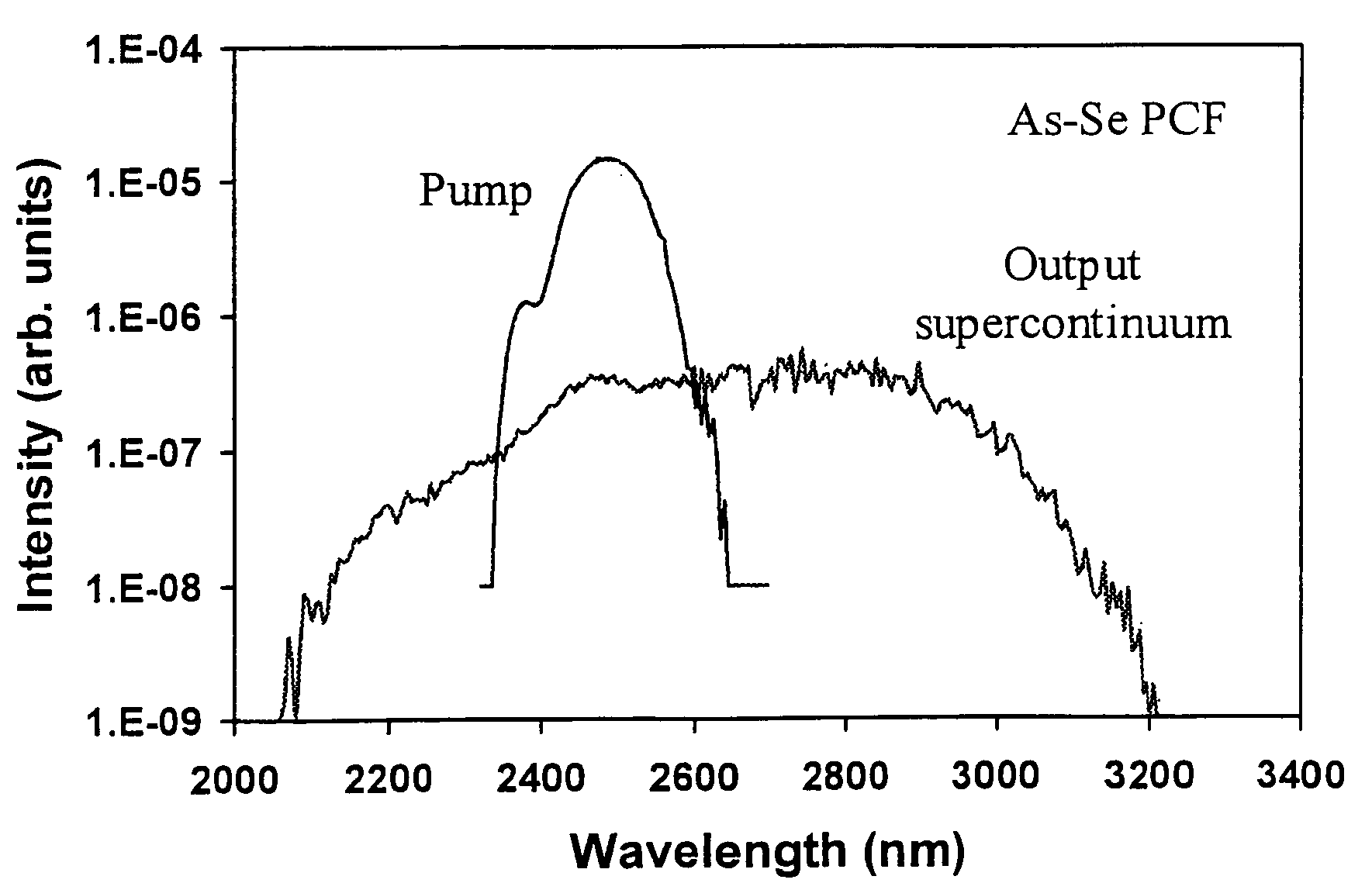
[0047]This example demonstrates generation of a supercontinuum using a photonic crystal As—Se glass fiber with a pulse laser light source.

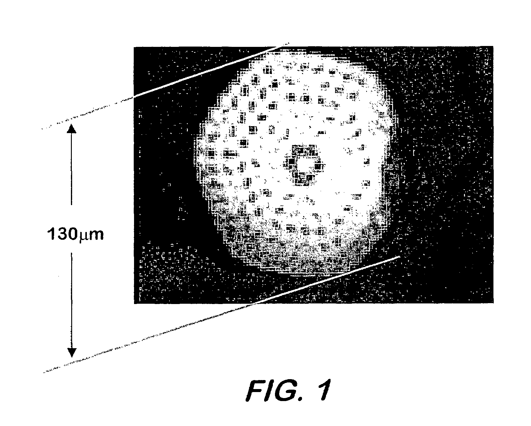
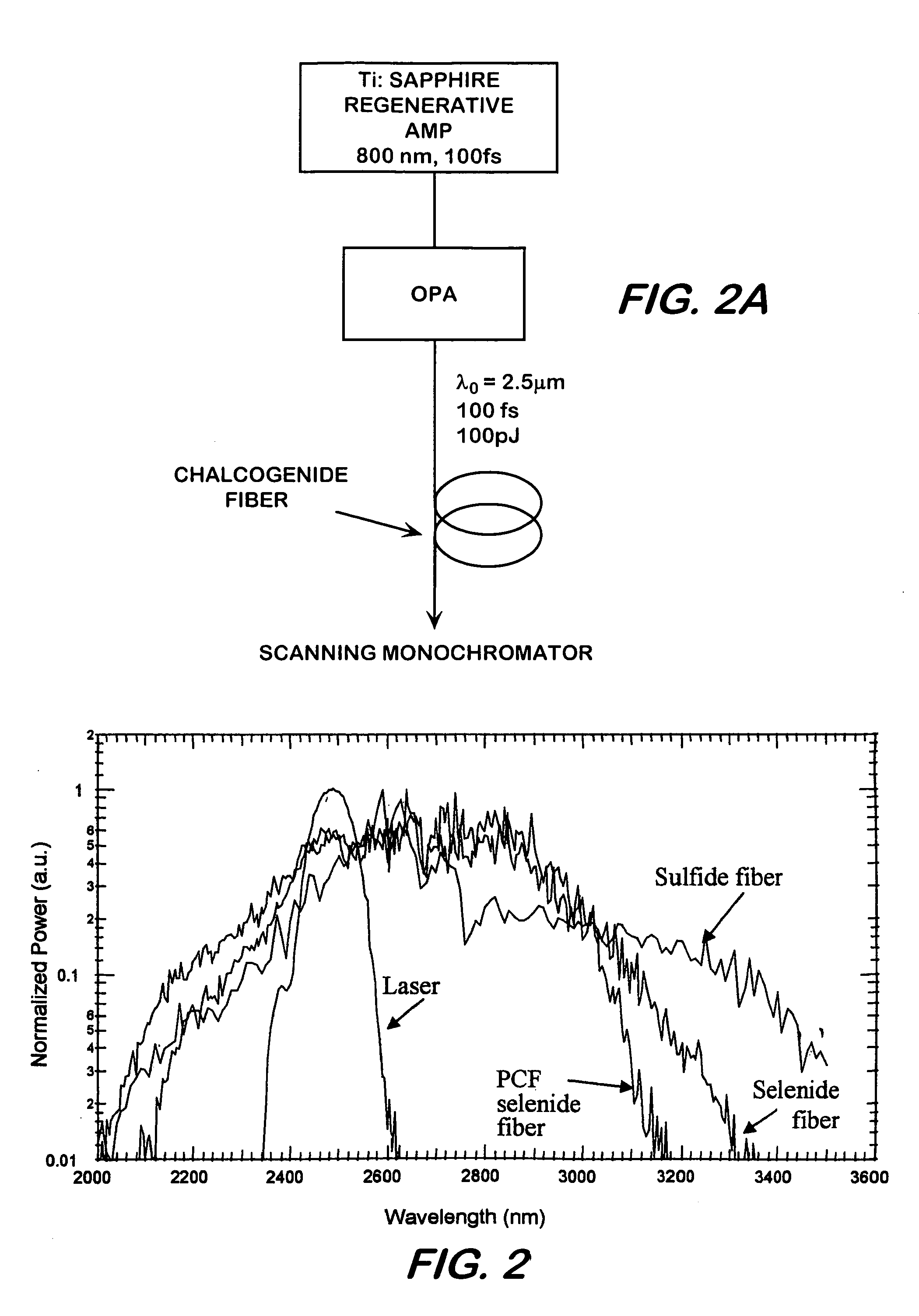
[0048]An infrared supercontinuum source consisted of a short pulse infrared pump source and a section of chalcogenide photonic crystal fiber whose dispersion minimum was at a wavelength of about 6 μm, as calculated, was matched as well as it could be to the wavelength of the pump source. FIG. 3 shows a schematic of the supercontinuum source wherein pump wavelength was 2500 nm, 80 fs pulses at power of less than 1 μJ per pulse. The chalcogenide fiber in the supercontinuum source was As—Se based photonic crystal fiber whose cross-section is shown in FIG. 1. The photonic crystal fiber O.D. was about 130 μm and the core size was about 10 μm. Fiber optical loss at 1.5 μm was 4.8 dB / m and the NA was about 0.45. As—Se fiber is highly transmissive in the infrared out to about 11 μm and thus, the generated supercontinuum shown in FIG. 4 was not limited by ...

example 2

[0050]This example demonstrates generation of a supercontinuum using a solid core As—Se glass fiber and a pulsed laser light source.

[0051]The same laser pump source was used here as in Ex. 1, operating at about 2500 μm. The pump was launched into 1 meter length As—Se glass fiber with a core size of about 7 μm and the optical fiber loss was on the order of about 1 dB / m at 1.5 μm wavelength. FIG. 5 shows the bandwidth of the supercontinuum at the output of the fiber.

example 3

[0052]This example demonstrates generation of a supercontinuum using a solid core of about 7 μm in diameter. As—Se glass fiber and a continuous wave laser.

[0053]FIG. 6 shows a broadband supercontinuum extending from about 5900 nm to about 6500 μm generated in an As—Se solid core from a continuous wave CO laser pump at about 5400 nm.


PUM


Abstract

This invention pertains to a device for broadening optical wavelength in the 2–14 μm region comprising a light source and a highly nonlinear chalcogenide fiber associated therewith whereby a light signal is passed from the light source into the fiber wherein and through interactions between the light signal and the material, bandwidth of the light signal is broadened in the 2–14 μm region.

Description

BACKGROUND OF THE INVENTION[0001]1. Field of the Invention[0002]This invention pertains to optical supercontinuum generation or broadening of bandwidth of an optical signal whereby wavelength of the signal is broadened between about 2 and 14 microns.[0003]2. Description of Related Prior Art[0004]In supercontinuum generation, pulses of femtoseconds (fs) to nanoseconds (ns) are spectrally broadened by various nonlinear processes, including self phase modulation, stimulated Raman scattering and four wave mixing, dependent on the pump temporal properties and the dispersion slope of the fiber to create a light continuum much broader in wavelength than the pump bandwidth. While supercontinuum generation is possible by focusing a high intensity light into a nonlinear medium, much broader bandwidths and significantly lower thresholds are possible when the pump is focused into an optical fiber where the guiding characteristics of the fiber allow long pump interactions with the nonlinearities...

Claims


Application Information

Patent Timeline
Patent Type & Authority Patents(United States)
IPC IPC(8): G02B6/00H01S3/00
CPCG02B6/02214G02F1/3555G02F1/365G02B6/02347G02F2001/3528G02F1/3528
Inventor SHAW, LESLIE B.SANGHERA, JASBINDER S.AGGARWAL, ISHWAR D.THIELEN, PETER A.KUNG, FRED
Owner THE UNITED STATES OF AMERICA AS REPRESENTED BY THE SECRETARY OF THE NAVY
Why Eureka
Try Eureka