Feedback estimation of joint forces and joint moments

a joint force and moment technology, applied in the field of human motion analysis, can solve the problems of imperfect experimental observations, noise pollution, and error caused by calculating higher-order derivatives, and achieve the effect of improving joint load estimation accuracy and reducing source of errors

Active Publication Date: 2006-11-14
HONDA MOTOR CO LTD
View PDF4 Cites 31 Cited by
  • Summary
  • Abstract
  • Description
  • Claims
  • Application Information

AI Technical Summary

Benefits of technology

[0012]In another embodiment, joint loads are recursively estimated for a planar serial link system. In a recursive method, one starts at a first end of a serial chain of segments and calculates joint loads towards a second end of the serial chain. Segments in the chain are connected together by joints and the reaction forces and moments at the joint are shared by the two connected segments. The joint loads estimated for a first segment are used in the estimation for the next segment until the joint or joints in interest are reached. That is, the output of a recursion is a force and moment calculation at the connection point for the next segment. This output is used as an input for the analysis of the next segment. A recursive method, therefore, does not require modeling the dynamics of the whole body. Although in a particular case it may be desirable to model recursively whole body dynamics, the recursive method provides flexibility that can reduce sources of error.
[0013]Recursive embodiments include open chain estimations and closed chain estimations. An open chain system is constrained with the environment at one end, and the remaining terminal segments are free. A closed chain system has more than one end in contact with the environment. The segments of the link system are numbered in order of recursion beginning with segment 1 toward segment n, which is the last segment of interest. Segment n is not necessarily the last segment in the multi-body system. Rather segment n is denoted the segment at which it is desired to stop the recursive computation such that the forces and moments of interest are found. In order to initiate the recursion, one requires the force and moment acting at the first segment. For example, in human motion analysis, the ground reaction forces under the feet are typically measured and initiate the recursion equations. The use of the ground reaction forces improves the precision of joint load estimates at the joints in proximity to the ground.

Problems solved by technology

Inverse dynamics analysis is conventionally applied to biomechanics problems because the internal forces of human joints cannot be readily measured.
A problem with using inverse dynamics in the study of human motion is the error caused by calculating higher order derivatives to determine joint forces and joint moments.
Experimental observations, however, are imperfect and contaminated by noise.
Sources of noise include the measurement device and the joint itself.
The result of this parabolic noise amplification is erroneous joint force and joint moment calculations.
Although techniques exist for filtering the noise, filtering is difficult and time-consuming because much analysis is required to separate the true signal in the biomechanical data from the noise.
A difficulty in low-pass filtering, however, is the selection of an optimal cutoff frequency fc.
Because there is no general solution for selecting optimal filter parameters, filtering techniques often produce unreliable results.
However, the application of optimization-based solutions is limited because the methods are computationally expensive, are not guaranteed to converge, and are generally too complex to implement.
Another problem with using inverse dynamics for analyzing human motion is that the inverse technique lacks the capability to predict the behavior of novel motions.
An inverse dynamics analysis lacks predictive capability because forces and moments are calculated rather than the expected response from the application of those forces and moments.

Method used


Image

  • Feedback estimation of joint forces and joint moments
  • Feedback estimation of joint forces and joint moments
  • Feedback estimation of joint forces and joint moments

Examples


Embodiment Construction

[0041]Preferred embodiments of the present invention are now described with reference to the accompanying figures where like reference numbers indicate identical or functionally similar elements. Also in the figures, the left most digit of each reference number corresponds to the figure in which the reference number is first used.

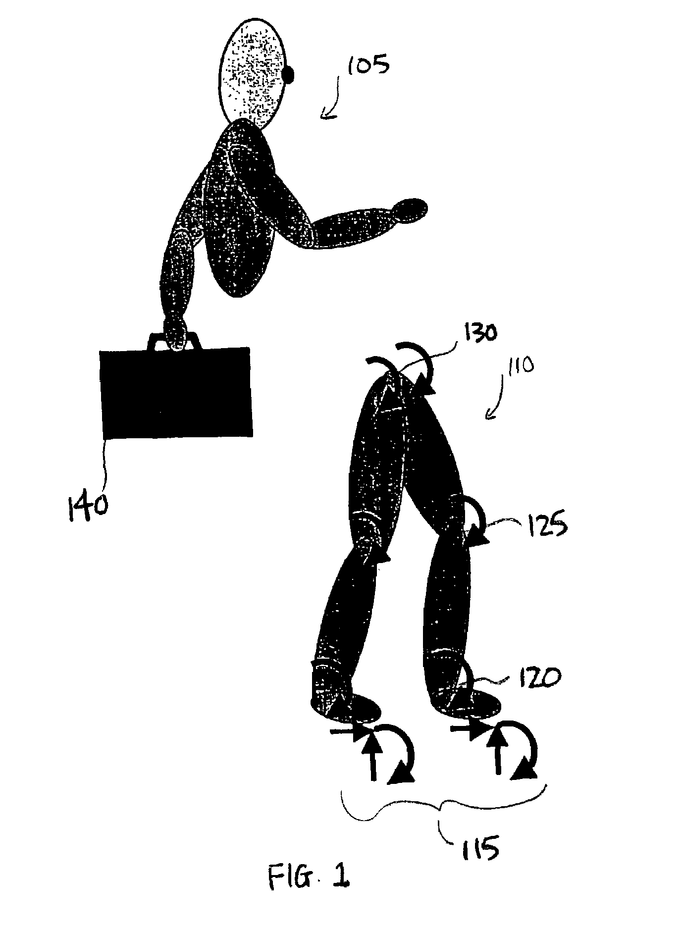
[0042]FIG. 1 is an illustration showing how recursive calculation is used to separate lower body dynamics from upper body dynamics. The illustration includes upper body portion 105 and lower body portion 110. A segment of upper body portion 105 is illustrated with load 140. Lower body portion 110 includes segments having ankle joint 120, knee joint 125, and hip joint 130. In a recursive method for computing joint forces and moments, the upper body portion 105 can be modeled separately from the lower body portion 110. Starting with ground reaction forces 115, one can effectively isolate joints 120, 125, and 130 of lower body portion 110 as well as the associ...


PUM


Abstract

Apparatus and methods are provided for estimating joint forces and moments in human beings. A forward dynamics module determines simulated kinematic data. An error correction controller forces tracking error between the simulated kinematic data and measured (or desired) kinematic data to approach zero. The error correction controller generates a modified acceleration for input into an inverse dynamics module. The estimated joint forces and moments track the measured (or desired) kinematics without the errors associated with computing higher order derivatives of noisy kinematic data.

Description

CROSS-REFERENCE TO RELATED APPLICATIONS[0001]This application is related to U.S. provisional patent application Ser. No. 60 / 301,891, filed on Jun. 29, 2001, entitled “A recursive, nonlinear feedback approach to estimate joint forces and joint moments from kinesiological measurements,” and U.S. provisional patent application Ser. No. 60 / 353,378, filed on Jan. 31, 2002, entitled “Forward solutions to inverse dynamics problems: a feedback linearization approach,” from which priority is claimed under 35 U.S.C. § 119(e) and both of which are incorporated by reference herein in their entireties.BACKGROUND OF THE INVENTION[0002]A. Field of the Invention[0003]This invention relates to human motion analysis and, more particularly, to analysis of joint forces and moments using nonlinear feedback in a forward dynamic simulation.[0004]B. Description of Background Art[0005]In the study of human motion, inverse dynamics analysis is conventionally used to estimate joint forces and joint moments. I...

Claims


Application Information

Patent Timeline
Patent Type & Authority Patents(United States)
IPC IPC(8): A61B5/117G06G7/48G06G7/58A61B5/103G06F19/00
CPCA61B5/1038A61B5/4528A61B5/103
Inventor DARIUSH, BEHZAD
Owner HONDA MOTOR CO LTD
Why Eureka
Try Eureka