Magnetically-actuable intramedullary device

a technology of intramedullary devices and magnetic actuators, which is applied in the field of magnetic actuators of orthopedic implants, can solve the problems of unidirectional axial movement and obtained bone lengthening or shortening, and achieve the effects of promoting accelerated bone healing, increasing the length of bone, and decreasing the length of bon

Inactive Publication Date: 2006-11-14
ORTHOGON TECH 2003 LTD
View PDF21 Cites 149 Cited by
  • Summary
  • Abstract
  • Description
  • Claims
  • Application Information

AI Technical Summary

Benefits of technology

[0037]It is to be noted that the term “essentially unidirectional”, as used hereinabove, is employed to indicate that although the main mode of axial movement is in one direction only, the device of the invention will also permit low-amplitude bidirectional, oscillatory, movement for the purposes of promoting accelerated bone healing.
[0038]In one embodiment of the device, the direction of ...

Problems solved by technology

It was further found that the accelerated healing effect occurs when the axial movement of the telescopic device is bidi...

Method used


Image

  • Magnetically-actuable intramedullary device
  • Magnetically-actuable intramedullary device
  • Magnetically-actuable intramedullary device

Examples


second embodiment

[0131]The invention does not require cylindrical or tubular implant sections but only that the first section telescope into the second section regardless of their cross sectional geometry. What is essential to the invention is that the first section functions as a permanent magnet and that the second section be non-magnetic so that when the implant installed in the complementary sections of the severed bone is subjected to an impulse of magnetic force, this will induce the first section to incrementally lengthen the implant and thereby lengthen by one step the severed bone.

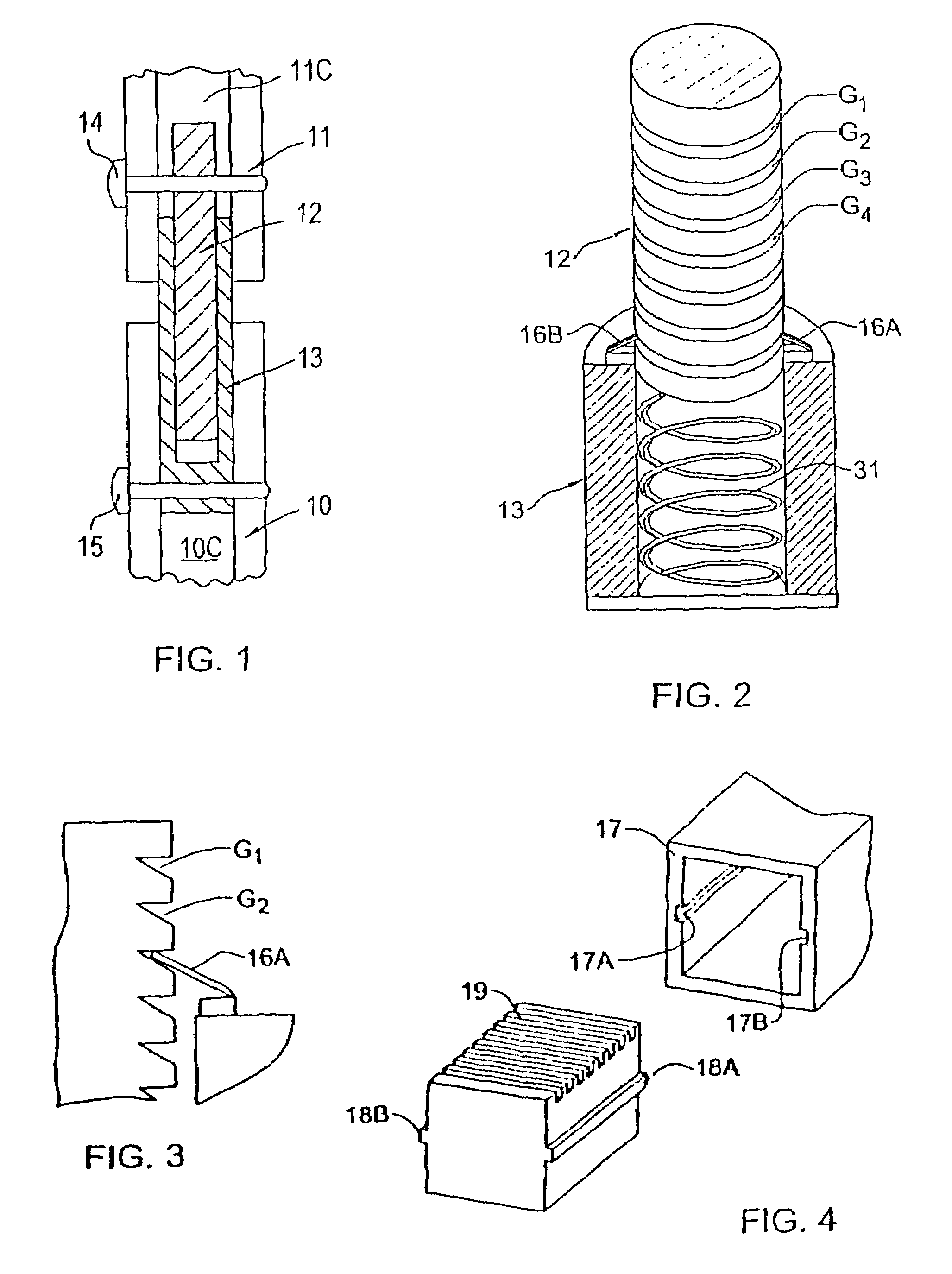
[0132]Thus the implant shown in FIG. 4 includes a non-magnetic section 17 which is channel-shaped and therefore has a rectangular cross section. Formed in the parallel sidewalls of this section are longitudinally extending grooves 17A and 17B.

[0133]Telescopically received in section 17 is a magnetic core section 18 having a square cross section that matches the cross sectional area between the sidewalls of section...

third embodiment

[0159]Instead of using the implant to lengthen a bone, it can be adapted to shorten a bone to a desired extent. To this end, a short piece of bone to be shortened is excised to provide a relatively large gap between the ends of the complementary bone sections. The ferromagnetic core section of the implant is then lodged in one of these bone sections and the non-magnetic socket section in which the core is telescoped is lodged in the other bone section.

[0160]Then by applying an external magnetic force thereto, the core section of the implant is caused to advance an incremental step further into the socket section, thereby reducing the gap between the bone sections. This action is repeated until the shortened distance between the ends of the bone section provides a bone of the desired shortened length.

[0161]When the implant is adapted to shorten a bone, the detenting of the core section must be such as to permit its stepwise advance into the socket section and prevent retrograde movem...

fourth embodiment

[0162]An orthopedic implant adapted to transport a bone fragment requires a ferromagnetic core the opposite ends of which are telescoped within respective non-magnetic sockets. These sockets are lodged in the complementary ends of the severed bone sections.

[0163]When a magnetic force is applied to the implant, the core is then advanced to step further into one socket and at the same time to step further out of the other socket without changing the length of the bone, for the distance between the ends of the complementary bone section remains unchanged.

[0164]In this way, a bone fragment may be transported from one bone section to the other in a direction that depends on the polarity of the magnetic force applied to the core.

[0165]While there have been disclosed preferred embodiments of the invention, it is to be understood that many changes may be made therein without departing from the spirit of the invention. Thus the implant may be used not to lengthen a bone but as a splint to ma...


PUM


Abstract

The present invention provides a two-part telescopic intramedullary orthopedic device comprising a first section inserted into the medullary cavity of one of the fractured or severed bone ends, and secured thereto, and a second section inserted into the medullary cavity of the other fractured or severed bone end and secured thereto, wherein the first section is telescoped within the internal space of the second section, and wherein one of the sections comprises a ferromagnetic material and the other section is either constructed entirely of a non-magnetic material or comprises a ferromagnetic material, wherein the ferromagnetic section(s) are actuable by an external axially directed magnetic field, such that one section may be caused to move axially (either bidirectional or essentially unidirectional) in relation to the other section. In addition, the invention encompasses a method for changing bone length as well as a method for enhancing bone fracture healing.

Description

[0001]This application is the US national phase of international application PCT / IL02 / 00401, filed in English on 22 May 2002, which designated the US. PCT / IL02 / 00401 claims priority to IL Application No. 143334, filed 23 May 2001 and IL Application No. 147156, filed 18 Dec. 2001. The entire contents of these applications are incorporated herein by reference.FIELD OF THE INVENTION[0002]The present invention relates generally to a magnetically-actuated orthopedic implant for use in promoting the healing of bone fractures and in manipulating bone length. More particularly, the present invention relates to an intramedullary device capable of changing its length in a cyclic manner under the influence of an electromagnetic field, said device being particularly suitable for the treatment of cases in which there is non-union of the fractured bone ends, as well as for the primary treatment of long bone fractures.BACKGROUND OF THE INVENTION [0003]The use of implant devices in the management o...

Claims


Application Information

Patent Timeline
IPC IPC(8): A61B17/56A61B17/58A61F2/28A61B17/72
CPCA61B17/7216
Inventor KOSASHVILI, YONAROBINSON, DROR
Owner ORTHOGON TECH 2003 LTD
Why Eureka
Try Eureka