Thermodynamic resonance enclosure

a technology of thermodynamic resonance and enclosure, which is applied in the field of enclosures, can solve the problems of requiring large amounts of electric or other energy to operate according to the design, affecting the comfort of the occupants of the residence, and affecting the comfort of the occupants, so as to achieve the effect of maximum thermodynamic resonance, minimal construction experience, and convenient us

Inactive Publication Date: 2006-11-14
DIMMICK WALTER F
View PDF12 Cites 24 Cited by
  • Summary
  • Abstract
  • Description
  • Claims
  • Application Information

AI Technical Summary

Benefits of technology

[0020]Another object of the present invention is to provide a thermodynamic resonance enclosure which is tunable to maximize the benefits of thermodynamic resonance within the enclosure.
[0021]Another object of the present invention is to provide a thermodynamic resonance enclosure which utilizes a minimum amount of energy to maintain a thermally controlled environment therein that is comfortable, while an environment outside of the enclosure is uncomfortably cool.
[0022]Another object of the present invention is to provide a thermodynamic resonance enclosure which can be constructed from readily available materials and which is easy to use with a minimum of construction experience required for the user.

Problems solved by technology

The delivery of these natural resources to residences in the form of hydrocarbon gases, heating oil or electricity, largely generated from combustion of such hydrocarbon fuels, involves considerable expense for the occupants of the residence.
However, the entire residence, or significant portions thereof, are typically heated during this time period, resulting in significant heat waste.
Such prior art enclosures suffer from requiring very large amounts of electric or other energy to operate according to their designs.

Method used


Image

  • Thermodynamic resonance enclosure
  • Thermodynamic resonance enclosure
  • Thermodynamic resonance enclosure

Examples


example 1

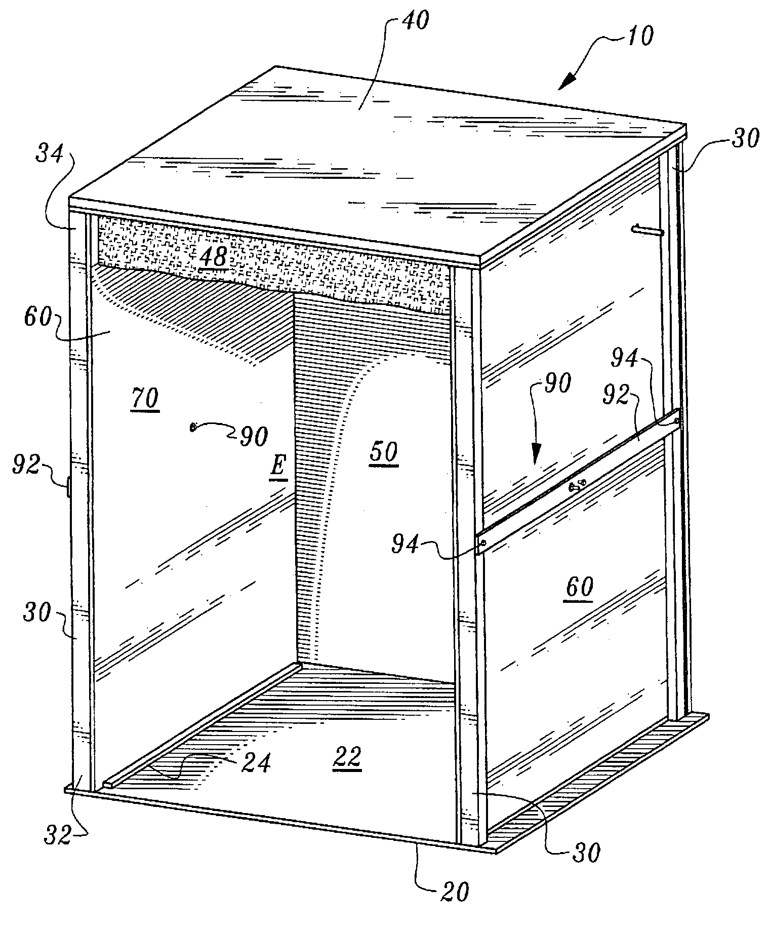
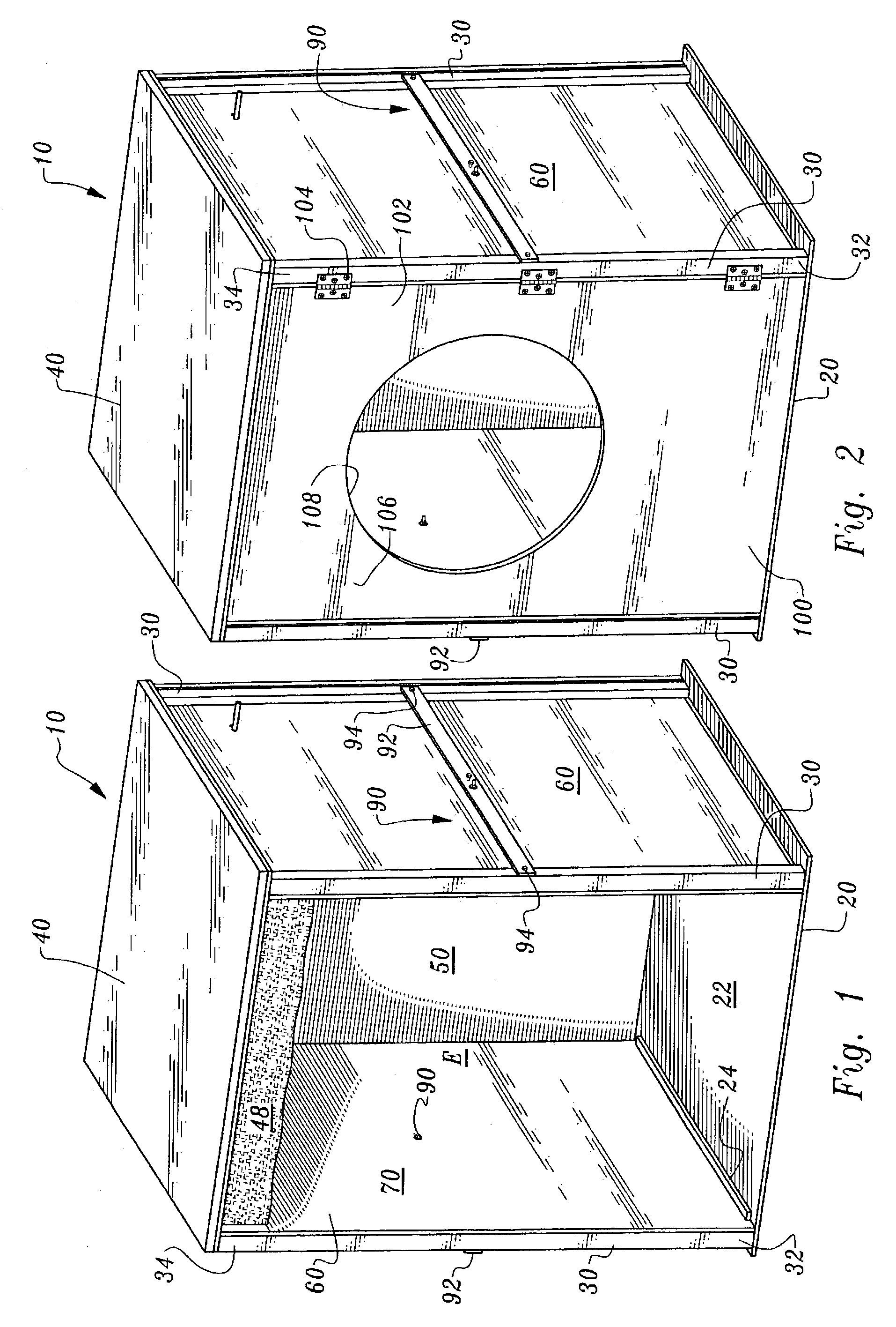
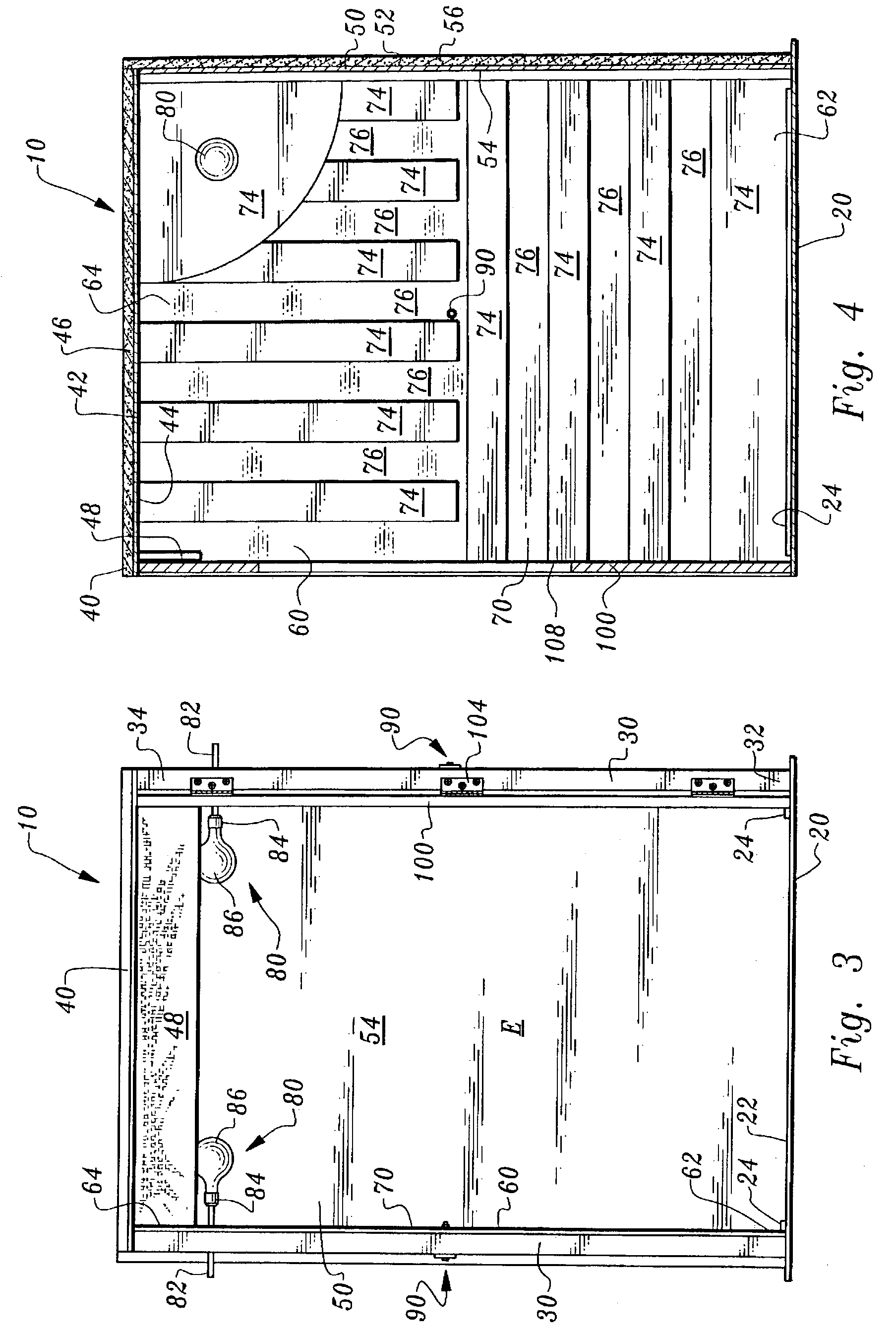
[0073]An enclosure has interior dimensions of 1.5 hydrogen cubits (H. C.) or approximately 37 9 / 16 inches in width, 2.5 hydrogen cubits (H. C.) or approximately 62 9 / 16 inches in height and 1.5 hydrogen cubits in depth. The sides and rear wall consist of ½ inch thick composition board with a paper veneer-like finish. The interior of the side is lined with 0.006 inch thick copper foil. The interior is partially lined with 0.006 inch thick copper foil consisting of an 18.75 inch radius quarter circle in the upper rear corner, plus vertical four inch wide strips of copper foil and horizontal four inch wide strips of copper foil. The interior of the back of the box is partially lined with 0.006 inch thick copper foil consisting of two 18.75 inch radius quarter circles, one in each upper corner of the back of the box. The remainder of the back of the interior of the box is lined with a heat reflecting material consisting of 0.0005 inch thick plastic, coated with aluminum or silver (silve...

example 2

[0086]A second enclosure is provided larger than the box / enclosure of example 1. This box has interior dimensions of two hydrogen cubits or about 50 1 / 16 inches wide, 2½ hydrogen cubits or about 62 9 / 16 inches high and about forty-eight inches long. This box has a front door which closes most of the front of the box but leaving approximately a two inch wide slit at one side of the door for ventilation. The door is hinged at one side to provide easy access to the box. The door has a forty-two inch diameter circular window disposed about at the center of the door. The door is made of approximately ½ inch thick plywood and the window is ½ inch thick glass. The sides and rear wall of the box are made of ¼ inch thick pressed hard board referred to by the trademark Masonite.

[0087]One inch thick polystyrene foam plastic sheets are cemented to the exterior of these Masonite panels for insulation. Since the Masonite panels have a tendency to warp or oil-can a little, means are provided for m...

example 3

[0101]The box of example three is a horizontal version of the box / enclosure concept designed for lying down and sleeping rather than sitting up and watching television, reading or working. The interior dimensions are 1½ hydrogen cubits high (about 37 9 / 16 inches) by 1½ hydrogen cubits wide by three hydrogen cubits long (75 plus inches). Similar to the enclosure of example two, the enclosure of example three is constructed of dimensionally stable material such as plywood or Masonite, lined on the outside with foam plastic insulation board or other appropriate insulation material and lined on the inside with heat reflecting material such as aluminum foil, copper foil, heat reflecting paint or sheet plastic coated with a good infrared reflecting material such as aluminum, silver or gold. The heat reflecting lining material on the interior top of ceiling of the box is thicker than the material on the sides so it is a good conductor of heat as well as a good reflector of heat. The heat r...


PUM


Abstract

An enclosure is provided generally in the form of a box which provides a controlled thermal environment for the occupant. The enclosure includes a horizontal base supporting four corner posts extending vertically up from the base, with a roof above the posts and parallel with the base. A rear wall extends in a vertical plane from the base up to the roof. A pair of side walls extend from the base up to the roof. The side walls preferably include surfaces to maximize maintenance of heat within the enclosure particularly near a position for an occupant's head. Thermal sources (i.e. incandescent light bulbs) are located within the enclosure to increase an amount of infrared radiation for heating within the enclosure. A width tuning system is provided to precisely position a distance of the side walls away from each other so that thermodynamic resonance between the side walls can be maximized.

Description

FIELD OF THE INVENTION[0001]The following invention relates to enclosures for maintaining a controlled thermal controlled environment therein, such as to provide a comfortable environment for human occupation while conserving energy necessary to maintain a desirable temperature within the enclosure. More particularly, this invention relates to enclosures which are sized, shaped and otherwise outfitted to utilize thermodynamic resonance to efficiently maintain a comfortable environment for human occupancy therein.BACKGROUND OF THE INVENTION[0002]Significant natural resources are spent in maintaining comfortable thermal environments for human occupancy, particularly in low temperature climates. The delivery of these natural resources to residences in the form of hydrocarbon gases, heating oil or electricity, largely generated from combustion of such hydrocarbon fuels, involves considerable expense for the occupants of the residence. Much of this energy is expended to maintain a comfor...

Claims


Application Information

Patent Timeline
Patent Type & Authority Patents(United States)
IPC IPC(8): A61N5/06E04B7/16
CPCA61N5/06A61H33/06A61N2005/064
Inventor DIMMICK, WALTER F.
Owner DIMMICK WALTER F
Why Eureka
Try Eureka