Static charge neutralizing assembly for use on rollers and shafts

Active Publication Date: 2006-11-14
ILLINOIS TOOL WORKS INC
View PDF23 Cites 73 Cited by
  • Summary
  • Abstract
  • Description
  • Claims
  • Application Information

AI Technical Summary

Benefits of technology

[0013]An advantage of the present invention is providing a static charge neutralizing device that does not require intimate contact between the device and a rolling surface such as a shaft or roller and therefore is not prone to wear and failure.
[0014]Another advantage of the present invention is providing a static charge neutralizing device particularly effective for use on three-phase motor shafts.
[0015]Still another advantage of the present invention is providing a static charge neutralizing device that can be used on roll

Problems solved by technology

A disadvantage from the use of such non-conductive bearings on rollers and shafts is that static charges are generated and stored in the roller or shaft, particularly under high speed operating conditions.
It is known in such installations that the static charge may reach twenty thousand volts, and can destroy critical electronic components near the conveyer roller or shaft, and may shock personnel in close proximity thereto.
Arcing creates potential danger to persons nearby and can cause damage to nearby components, including sputtering of metal from the bearing races at the point of current flow, thus damaging the bearing.
A dis

Method used


Image

  • Static charge neutralizing assembly for use on rollers and shafts
  • Static charge neutralizing assembly for use on rollers and shafts
  • Static charge neutralizing assembly for use on rollers and shafts

Examples


Embodiment Construction

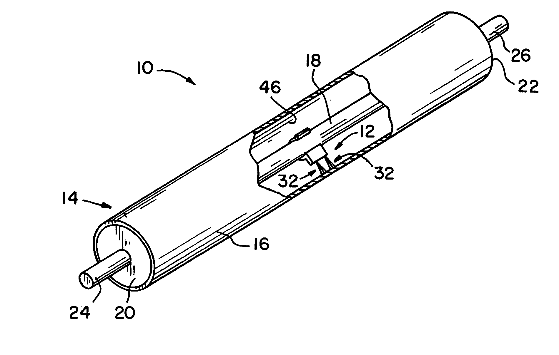
[0028]Referring now more specifically to the drawings and to FIG. 1 in particular, a roller assembly 10 is shown, including a static charge neutralizing assembly 12 of the present invention operatively installed on a roller 14 for dissipating the accumulation of static charge on roller 14. In the exemplary embodiment shown, roller 14 is a conveyor roller, but may be another roller type for another purpose.

[0029]Roller 14 includes a hollow shell 16 mounted for rotation on a shaft 18. Shell 16 includes ends 20 and 22 mounted by bearings (not shown) or the like on shaft 18, with shaft 18 extending completely through shell 16. End portions 24 and 26 of shaft 18 project outwardly of roller ends 20 and 22, providing structure by which roller 12 can be mounted in equipment or machinery for operation.

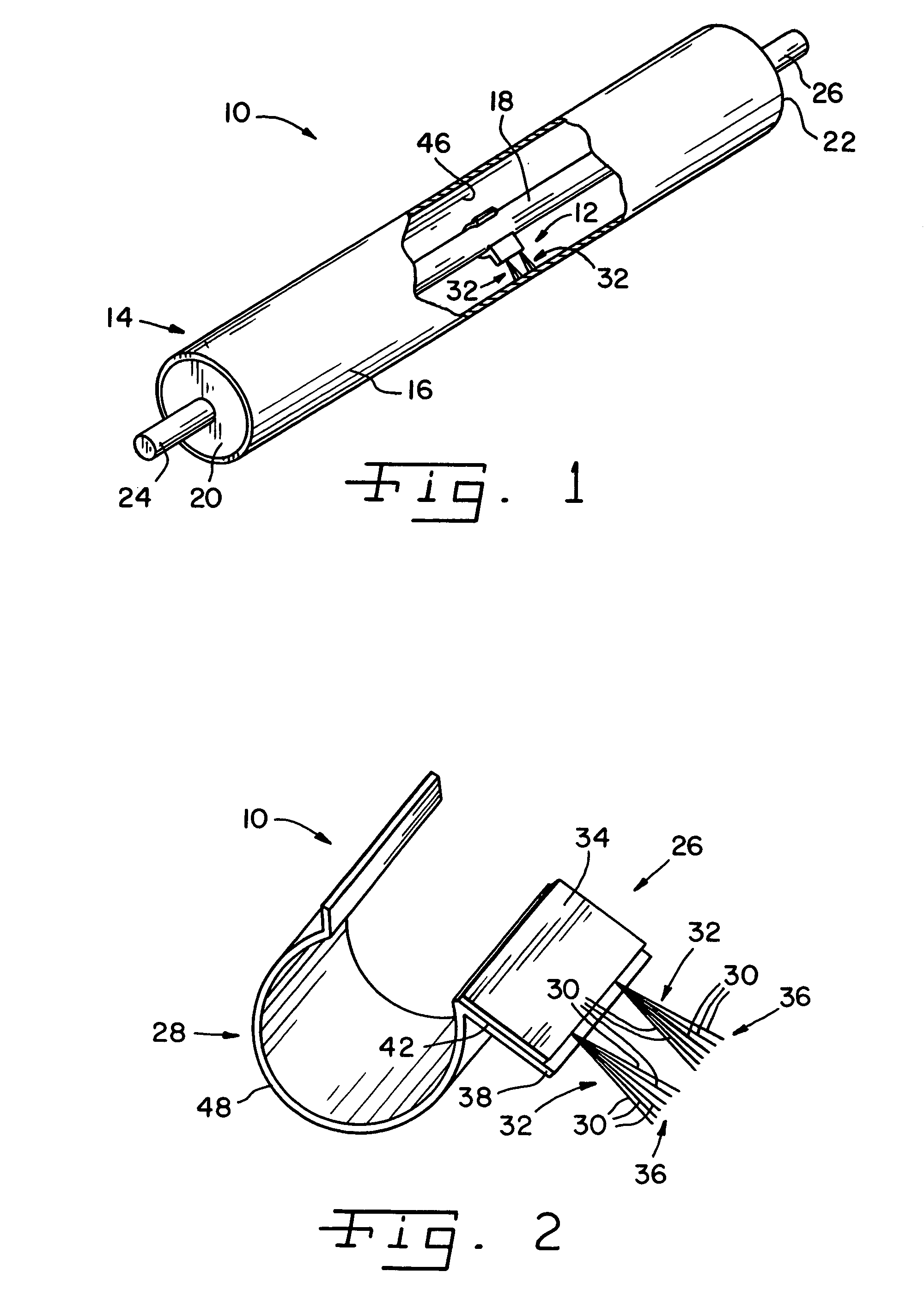
[0030]Static charge neutralizing assembly 12 is disposed within shell 16 and includes a mounting fixture 28 by which assembly 12 is attached to shaft 18. Neutralizing assembly 12 further includ...


PUM


Abstract

A static charge neutralizer for a moving component of an apparatus includes a plurality of filaments on a conductive strip, with tips of the filaments disposed adjacent but spaced from the moving component. The filaments induce ionization in the presence of an electrical field from the statically charged surface of the moving component.

Description

CROSS-REFERENCE TO RELATED APPLICATIONS[0001]The present regular application claims the benefit of U.S. Provisional Application Ser. No. 60 / 455,301, filed Mar. 17, 2003.FIELD OF THE INVENTION[0002]The present invention relates to static charge neutralizing devices used on rollers and shafts; and, more particularly, the invention relates to a non-contacting static charge neutralizing devices.BACKGROUND OF THE INVENTION[0003]It is known to use non-conductive bearings or sleeves in conveyor rollers and other rollers in various process equipment to provide non-corrosive assemblies and to reduce costs for such equipment. A non-conductive bearing is known to be composed of nylon, polyurethane or other synthetics for durability and anti-corrosion properties. Such non-metallic bearings do not require grease or other lubrication and are often preferred for machinery used in food processing equipment, medical supplies production facilities and other installations that require protection from ...

Claims


Application Information

Patent Timeline
IPC IPC(8): H05F3/00H01H47/00H05F3/02H02K11/00H05F3/04
CPCH02K11/0089H05F3/02H05F3/04H02K11/40
Inventor OH, HIEYOUNG W.KING, CHARLES A.MCCORMICK, DANIEL P.
Owner ILLINOIS TOOL WORKS INC
Why Eureka
Try Eureka