Wave-fans and wave-fans with heat sinks

a technology of wavefans and fans, applied in the direction of wind motor components, non-positive displacement fluid engines, liquid fuel engine components, etc., can solve the problems of high velocity, large fan requirements, noisy fans, etc., and achieve low profile design, good heat flow into the air, and high local velocity

Inactive Publication Date: 2006-11-14
HERBERT EDWARD
View PDF2 Cites 32 Cited by
  • Summary
  • Abstract
  • Description
  • Claims
  • Application Information

AI Technical Summary

Benefits of technology

[0009]The wave-fans of this invention do not comprise a plurality of blades, or airfoils, as in a conventional fan. The “wave-plane” and “wave-ring” fans comprise a wavy active surfaces of roughly sinusoidal contour along the direction of rotation with no openings between the ridges and valleys. The “wave-plane” fan is a flat fan, for use with a flat heat sink. The “wave-ring” fan is generally cylindrical with a wavy surface, for use with a cylindrical heat sink. Their function is to cause a pulsating fluid motion within a heat sinking means. As an example, not a limitation, the fluid may be air. Because the wave-fans are rotating, there will be a centrifugal component to the airflow. The pulsating air motion has very high local velocity, particularly as a ridge of the roughly sinusoidal contour passes a point on the heat sinking mean, to scrub away the boundary layer and effect good heat flow into the air. The comparatively low velocity airflow through the fan incidental to the centrifugal airflow carries the heated air away.
[0010]This arrangement has a number of benefits, among them a compact, low profile design, high efficiency, low noise and less susceptibility to dirt in the air. In some embodiments of the invention, the outer exposed surface is smooth, so they may be used in exposed locations without guards or housings. In the preferred embodiments of the invention, the centrifugal force on the air flowing through the fan is such that any contaminants tend to be thrown away from the heat sink, to greatly reduce the tendency of dust and so forth to clog the heat sink and reduce or eliminate the need for inlet air filters. Because the net air flow through the fan is much lower than in prior art fans, operation is very quiet and they requires less power.

Problems solved by technology

However, there is a boundary layer that is a very persistent viscous layer of air on the surfaces of the heat sink fins, requiring very high velocity and turbulent air flow to dissipate the boundary layer for heat flow into the air.
In prior art heat sinks, this required very large, powerful and noisy fans.

Method used


Image

  • Wave-fans and wave-fans with heat sinks
  • Wave-fans and wave-fans with heat sinks
  • Wave-fans and wave-fans with heat sinks

Examples


Embodiment Construction

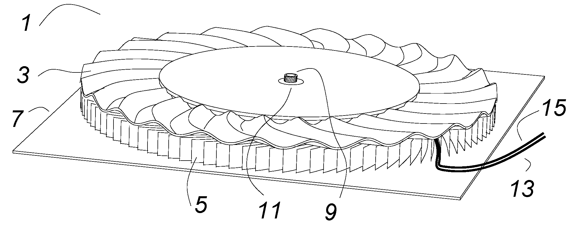
[0027]FIG. 1 shows a wave-fan with a heat sink 1 comprising a wave-fan that is a wave-plane fan 3 rotating above a flat finned heat sinking means 5. A motor means (not visible) turns the fan 3. A motor shaft 11 turns the fan 3. The whole is on a base plate 7 that is a “cold plate”. A tube 9 may run through the motor to locate and retain the motor and also to provide a vent access to the bottom surface of the base plate 7 to facilitate mounting to a heat source with vacuum. The fan 3 and the heat sink 5 are discussed in more detail below. Wires 13 and 15 may thread between fins of the heat sink 5 to provide power to the motor means (not visible).

[0028]The bottom surface of the wave-plane fan 3 comprises an active fluid moving surface comprises a plurality of ridges and valleys having a generally sinusoidal contour along the direction of rotation of the wave-plane fan 3. The top surface of the flat finned heat sinking means 5 is its active heat dissipating surface. The active surface ...


PUM


Abstract

A wave-fan comprises a wavy surface, generally sinusoidal in the direction of rotation, which rotates in close proximity to the fins of a heat sink. The wave-plane fan is suitable for use with a flat heat sink, and a wave-ring fan is suitable for use with a cylindrical heat sink. There are no airfoils as in a prior art fan. Instead, the ridges of the wave-fan agitate the air between the fins of the heat sink as each ridge passes, breaking down the boundary layer and effecting good heat flow into the air. In some embodiments of the wave-fan, the outer surfaces are smooth, so it is not a hazard to intruding fingers, so in many applications it may be used without a guard or enclosure. Incidental centrifugal force provides some airflow through the fan to transport the heated air away from the fan. Also, the configuration of the fan tends to keep contamination in the air out of the heat sink fins, so an inlet air filter may not be needed. Because the net airflow through the fan is low, less power is required and it is very quiet.

Description

CROSS REFERENCE TO RELATED APPLICATIONS[0001]This is a continuation in part application of a provisional patent application entitled: “Fan With Heat Sink”, Ser. No. 60 / 481,173, filed 4 Aug. 2003.BACKGROUND OF INVENTION[0002]U.S. Pat. Nos. 5,297,617 and 5,445,215, both entitled FAN WITH HEAT SINK, and owned by the same entity as this patent application, teach that the area surrounding the fan blade tips in an axial flow fan has high velocity, very turbulent air, and that the periphery of an axial flow fan is an excellent heat sink, particularly if the inside of the fan duct and / or the fan blade are modified as taught therein to enhance the heat sinking. These are modified axial flow fans, and the air flow through them may be partly or completely redirected to fins or other features in the periphery of the fan duct, to remove heat therefrom. These patents are incorporated herein by reference.[0003]Other related patent applications are: a provisional patent application entitled FAN WIT...

Claims


Application Information

Patent Timeline
Patent Type & Authority Patents(United States)
IPC IPC(8): H05K7/20
CPCF04D29/281F04D29/325F04D29/582H01L23/467H01L2924/0002H01L2924/00
Inventor HERBERT, EDWARD
Owner HERBERT EDWARD
Why Eureka
Try Eureka