
Neural transplantation delivery system

a neural transplantation and delivery system technology, applied in the field of neural transplantation in the human brain, can solve the problems of poor graft integration, reduced graft survival, cell death and cell death, and achieve the effect of optimizing the host reinnervation, reducing the number of passes through the brain, and maximizing the number of deposits

Inactive Publication Date: 2006-11-21
MENDEZ IVAR
View PDF5 Cites 21 Cited by
  • Summary
  • Abstract
  • Description
  • Claims
  • Application Information

AI Technical Summary

Benefits of technology

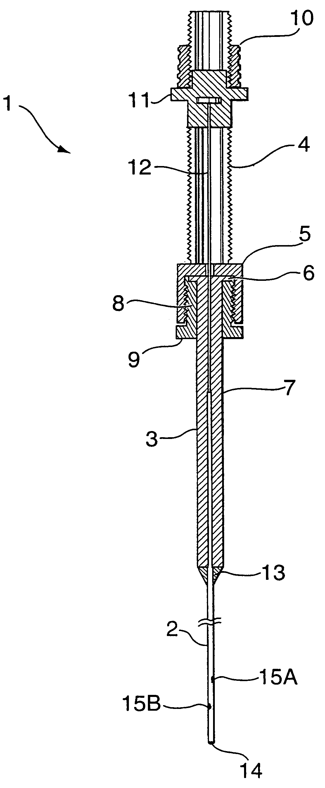
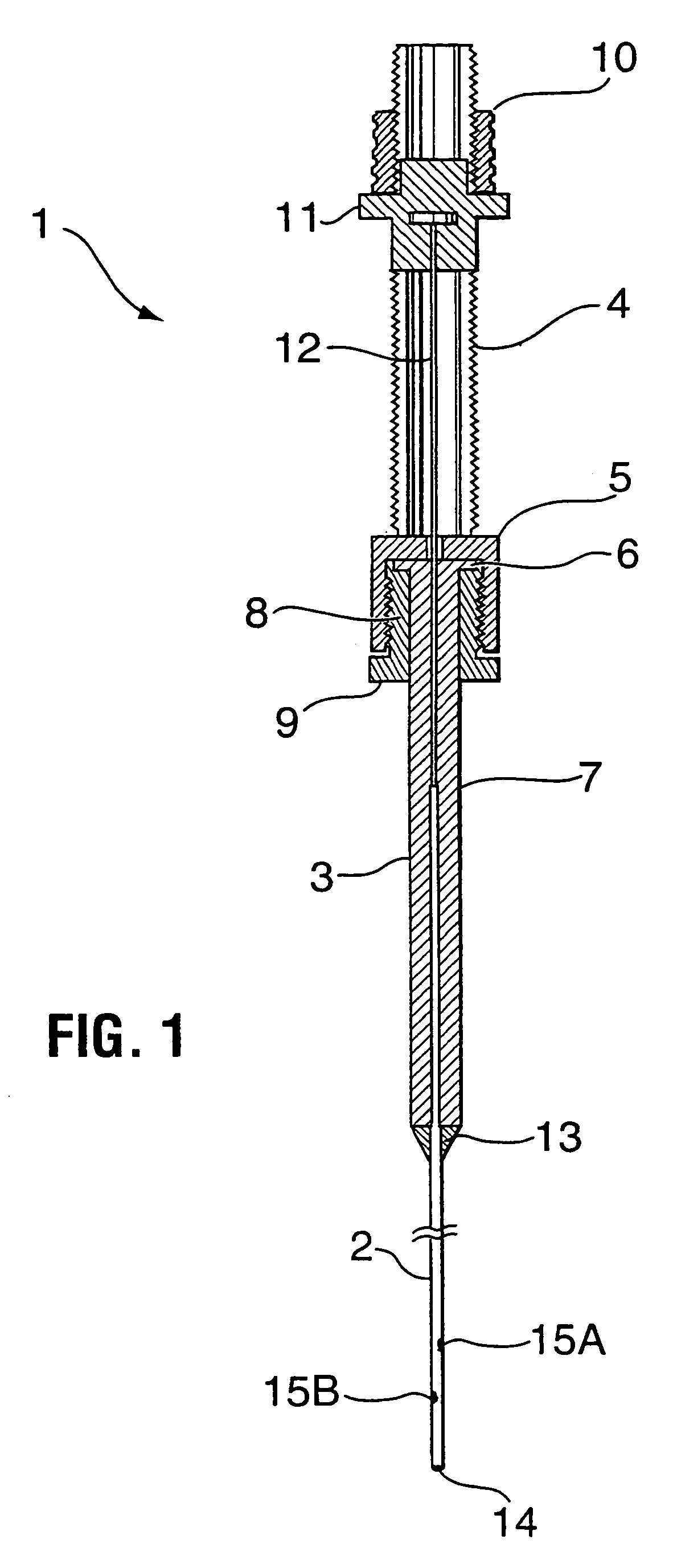
[0009]An object of the present invention is to provide a delivery system for neural transplantation grafts, comprising a microinjector and transplantation cannula, which facilitates delivery in a three dimensional configuration at a targeted site within a subject while undertaking a minimal number of penetrations into the host brain.
[0011]Another object of the invention is to provide a delivery system for neural transplantation grafts, comprising a microinjector and transplantation cannula, that can be easily incorporated with a syringe to facilitate reliable and safe neural transplantation of cell grafts to the human brain.

Problems solved by technology

Implantation trauma, which decreases graft survival, and inadequate reinnervation of the host striatum due to suboptimal distribution of graft deposits are considered detrimental factors in achieving optimal clinical efficacy.
In particular, because the outside diameter of the guide cannula is relatively large, e.g. 1.07 mm, the insertion of the guide cannula into the brain during standard neural transplant procedures has the potential to cause localized trauma to the tissue and ultimately result in cell death and poor graft integration.
Other disadvantages associated with a transplant cannula having a large diameter is a lower precision in graft placement and a lower reliablity in delivery of very small volumes to a selected site in a subject.
In addition, the design of this particular transplantation device only allows multiple grafts to be delivered along a single path with each insertion of the delivery cannula.
Although it is desirable to deliver multiple grafts along different paths in a three dimensional configuration, reinsertion of the cannula increases the risk of trauma to the brain of the transplant recipient with each new penetration thereby contributing to low and variable graft survival and functional recovery.
Furthermore, because the delivery cannula is deflected at an angle from the guide cannula and causes the delivery cannula to enter the brain tissue in an oblique fashion, this is also potentially harmful to the brain.
Another disadvantage of the Cunningham transplantation device is that the shape of the opening at the extreme distal end of the delivery cannula is not blunt and is potentially harmful to the brain.
Moreover, the opening of the tip of the delivery cannula has the potential to become obstructed in the course of performing multiple insertions of the delivery cannula, thereby eventually preventing ejection of a cell and / or tissue suspension.

Method used


Image

  • Neural transplantation delivery system
  • Neural transplantation delivery system
  • Neural transplantation delivery system

Examples


example 1

Animal Studies

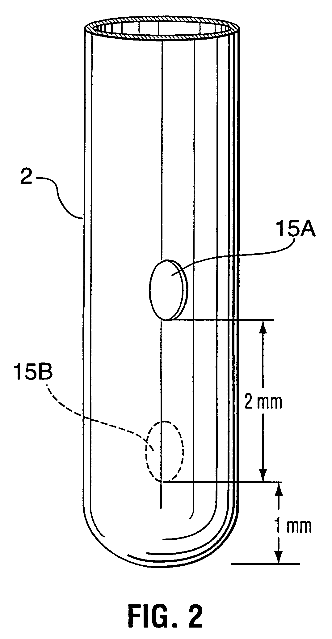
[0068]Animals tolerated the transplant procedure well and all of them had surviving grafts 6 to 8 weeks after transplantation. Typically, two graft deposits were observed in the implanted striatum and each graft deposit corresponded to the upper and lower side holes of the transplant cannula (FIG. 7). The cannula tract was clearly visible connecting the upper and lower graft and the deposits appear to be oriented in opposite directions. Numerous TH immunoreactive cells and fibres were observed in the graft deposits and cannula tract (FIG. 7). Fibres were also observed penetrating the host striatum for variable distances and overall the appearance of the grafts was comparable to animals grafted with a glass microcapillary in our laboratory (Mendez et al., Brain Res., 778, pp. 194–204, 1997; Mendez et al., J. Neurosci., 16(22), pp. 7216–7227, 1996). There was no evidence of significant trauma in the grafted area and no tissue disruption was observed in the cannula tract....

example 2

Clinical Studies

[0069]Eight patients enrolled in the Halifax Neural Transplantation Program received bilateral putaminal fetal VM tissue obtained from women undergoing elective abortions in the pregnancy termination unit of the Queen Elizabeth II Health Sciences Centre following strict guidelines of a protocol approved by the University and Hospital ethical review boards.

[0070]The surgical transplantation procedure was carried out in two stages in which each side was transplanted 4 to 6 weeks apart. Patients were admitted to hospital the night prior to surgery. On the day of surgery, patients were fitted with a Leksell stereotactic headframe under local anaesthesia. The stereotactic coordinates for targets in the putamen were calculated using T1-weighted MRI images and a computerized planning workstation (Surgiplan, Elekta AB, Stockholm, Sweden).

[0071]Transplantation was performed with the patient under local anaesthesia and sedation, using a combination of Midazolam (0.25 to 1.0 mg...


PUM


Abstract

A device and method for neural transplantation in the human brain comprising a microinjector (1), transplantation cannula (2) and bullet guide (16) is disclosed. The microinjector (1) is designed to connect to the proximal end of a syringe barrel (7) and plunger (12) while the transplantation cannula (2) interfaces with the distal end of the syringe barrel (7). In combination, the microinjector (1) and transplantation cannula (2) permit the delivery of multiple cell grafts in a three-dimensional array using a unique spiral technique. The bullet guide (16), which is attachable to a commercially available stereotactic frame, is a multiple channel adapter that functions as a mechanical guiding system for the transplantation cannula (2) and permits plural, spaced deployment of the cannula (2) without adjusting or disturbing the frame.

Description

FIELD OF INVENTION[0001]The present invention relates to a device and method for neural transplantation in the human brain comprising a microinjector, transplantation cannula and bullet guide. The microinjector and transplantation cannula are adapted to connect to opposite ends of a syringe in a simple manner. The bullet guide, comprised of mutually spaced top and bottom portions, is mounted to a stereotactic frame and functions as a mechanical guiding system for the cannula. In combination, the invention provides a simple, reliable and safe system for delivering and maximizing the number of cell graft deposits to the host brain with minimal trauma using a unique spiral technique.BACKGROUND OF THE INVENTION[0002]Neural transplantation of fetal ventral mesencephalic (VM) tissue has been studied for the past two decades as a potential surgical strategy for the treatment of Parkinson's disease (PD). Clinical trials in Parkinsonian patients have been conducted in several centres worldwi...

Claims


Application Information

Patent Timeline
IPC IPC(8): A61M5/00A61B90/11
CPCA61B17/3403A61B17/3478A61B19/201A61M2210/0693A61B90/11
Inventor MENDEZ, IVAR
Owner MENDEZ IVAR
Learn More