Screen

a technology for screens and luminances, applied in the field of screens, can solve the problems of difficult to improve the overall luminance of screens, difficult to achieve vertical uniform luminance distribution, and inefficient use of projected light, and achieve the effect of easy provision of screens with highly uniform luminances

Inactive Publication Date: 2006-11-21
SONY CORP
View PDF9 Cites 21 Cited by
  • Summary
  • Abstract
  • Description
  • Claims
  • Application Information

AI Technical Summary

Benefits of technology

[0013]Accordingly, to overcome the problems described above, the present invention provides a screen that has a simple structure, utilizes projected light efficiently, and has an improved luminance uniformity between the center and the periphery of the screen.
[0014]In a first aspect of the present invention, a screen that displays a projected light image has a layer for reflecting the light image, a diffusion layer for scattering the light reflected from the reflective layer, and a Fresnel lens between these two layers. This allows most of the light image at the periphery of the screen to be reflected to the viewer, thereby enabling an increase in screen gain and a uniform luminance distribution over the screen.
[0015]The diffusion layer may have elliptic diffusion properties, in which the longitudinal diffusion angle is different from the transverse diffusion angle. The FWHM longitudinal diffusion angle may be 10°–50°, and the FWHM transverse diffusion angle may be 60°–180°. In these screens, the directivity and the screen gain can be increased by reducing the longitudinal diffusion area, which requires a narrow viewable area. In addition, the viewed image can be improved by increasing the transverse diffusion area. Furthermore, the reduction in the longitudinal diffusion area results in less influence of incident light from above, and thus achieves higher contrast under strong illumination.

Problems solved by technology

Thus this screen uses projected light inefficiently and it is difficult to improve the overall luminance of the screen.
On the other hand, the screen that includes the coupled mirrors can have a horizontally uniform luminance distribution, but cannot have a vertically uniform luminance distribution because of its structure.

Method used


Image

  • Screen
  • Screen
  • Screen

Examples


first embodiment

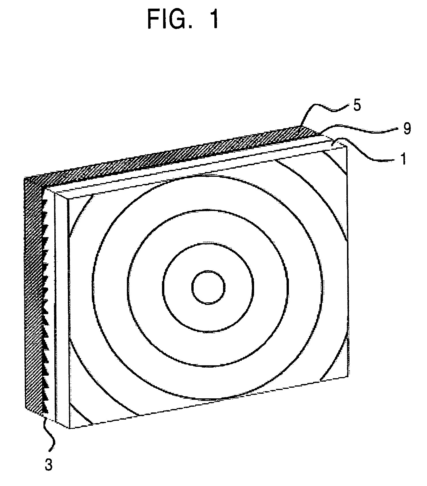
[0045]FIG. 1 shows a screen according to the present invention. A diffusion film 1, a Fresnel lens 3, and a reflective layer 5 are laminated from front to back.

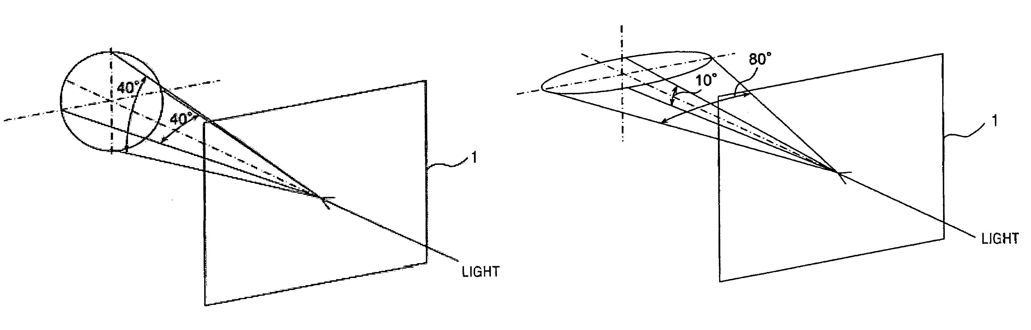
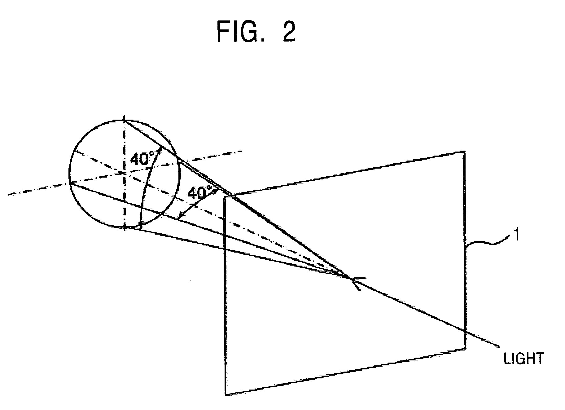
[0046]The diffusion film 1 is disposed at the front surface of the screen and scatters light reflected from the reflective layer 5 over a certain area. Examples of the diffusion film 1 include a diffusion film having a circular diffusion pattern with the same diffusion angle in the transverse direction and the longitudinal direction, as shown in FIG. 2, and a diffusion film having an elliptic diffusion pattern in which the longitudinal diffusion angle is smaller than the transverse diffusion angle, as shown in FIG. 3. For the diffusion film having a circular diffusion pattern, the FWHM in FIG. 4 is preferably 30°–60°, depending on the viewing angle required for the screen. FWHMs larger than 60° will increase ineffective diffusion outside the viewable area in the longitudinal direction and result in reduced screen gain. FIG. 2...

second embodiment

[0065]The screen has the same effect, as shown in FIGS. 12 and 13, only in the longitudinal direction owing to the refraction in the longitudinal direction by the linear Fresnel lens 23. Thus, the reflection of projected light is efficiently converged to the longitudinal viewable area without taking the transverse viewable area into consideration.

[0066]While only the linear Fresnel lens in the longitudinal direction is used in the second embodiment, a linear cross Fresnel lens, in which a linear Fresnel lens in the longitudinal direction and that in the transverse direction are attached to each other, may be used. In the linear cross Fresnel lens, since the magnification can be changed independently in the longitudinal direction and in the transverse direction, the reflected light can be efficiently converged to the longitudinal viewable area and the transverse viewable area. Thus, a high-performance, wide and large screen with uniform luminance can also be provided.


PUM


Abstract

A screen with an improved luminance uniformity is provided. A diffusion film that is disposed at the front surface of the screen is attached to a Fresnel lens with an adhesive. The Fresnel lens is attached to a reflective layer that is deposited on a base film with an adhesive that has a refractive index lower than that of the Fresnel lens and as low as possible.

Description

BACKGROUND OF THE INVENTION[0001]1. Field of the Invention[0002]The present invention relates to a screen with an improved luminance uniformity.[0003]2. Description of the Related Art[0004]In recent years, overhead projectors and front projectors have widely been used for presentations in meetings and conferences. Liquid crystal video projectors and moving-image projectors are also becoming widespread for household use. These projectors project light on a screen by modulating light from a light source via, for example, a transmissive liquid crystal panel to form a light image and emitting the light image through an optical system, such as lenses.[0005]For example, a projector that forms color images on a screen includes an illuminating optical system that separates light from a light source into red (R), green (G), and blue (B) and then converges them on a predetermined optical path; a liquid crystal panel that modulates each red, green, and blue flux separated by the illuminating o...

Claims


Application Information

Patent Timeline
Patent Type & Authority Patents(United States)
IPC IPC(8): G03B21/56G03B21/60G02B3/08G02B5/02G02B5/08G02B5/22H04N5/74
CPCG02B3/08G02B5/08G02B5/22G03B21/567G03B21/602G02B5/021G02B5/0278
Inventor CHUBACHI, HIDEYAHAYASHI, HIROSHIIKEDA, OSAMU
Owner SONY CORP
Why Eureka
Try Eureka