Eureka AIR delivers breakthrough ideas for toughest innovation challenges, trusted by R&D personnel around the world.

Image pickup lens

a technology of image pickup and lens, applied in the field of image pickup, can solve the problems of difficult to reduce the size, the one-lens system is not sufficient, and the three-lens system requires a large number of components, so as to achieve high optical characteristic and maintain productivity

Inactive Publication Date: 2006-11-21
ENPLAS CORP
View PDF13 Cites 2 Cited by
  • Summary
  • Abstract
  • Description
  • Claims
  • Application Information

AI Technical Summary

Benefits of technology

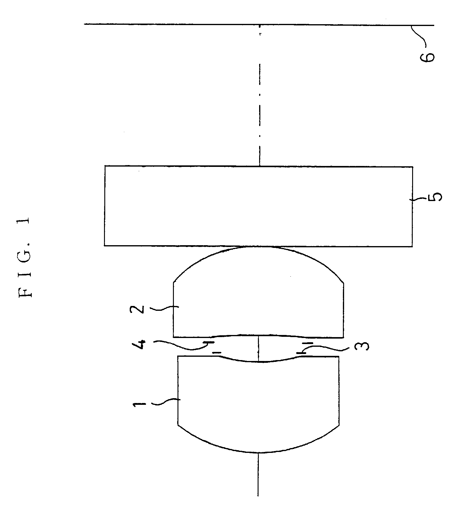
The present invention provides an image pickup lens that improves optical characteristics and productivity through increasing telecentricity and effective correction of coma aberration and distortion aberration. The lens comprises a first lens, a diaphragm, and a second lens, which satisfies specific conditions to maintain the distance between the exit pupil and the image pickup surface and effectively utilize the incoming ray to peripheral part of the sensor. The diaphragm is placed in the vicinity of the first lens to further ensure increased telecentricity and effective correction of aberrations. The first and second lenses are made of resin material and have aspherical faces to maintain high optical characteristic while keeping productivity.

Problems solved by technology

Such camera needs to be mounted on a limited space.
In order to sufficiently utilize the resolving power of the solid image pickup element with such high resolution, the conventional one-lens system is not sufficient.
However, the three-lens system requires a large number of components.
Thus, there raises problems that it is hard to reduce the size, and the manufacturing cost is increased since each component is required to be highly precise.
However, it is practically impossible to reduce the size as small as that of the one-lens system due to such structure with the long back focus distance.
However, the telephoto type lens system is originally developed for silver salt photographs so that the back focus distance is too short.
Further, there is an issue of telecentricity.
Thus, it is practically impossible to use it as the image pickup lens for the solid image pickup element.
However, it is not possible to apply the conventional image pickup lens with two lenses in which two lenses having positive power are combined as it is for the solid image pickup element.

Method used


Image

  • Image pickup lens
  • Image pickup lens
  • Image pickup lens

Examples


example 1

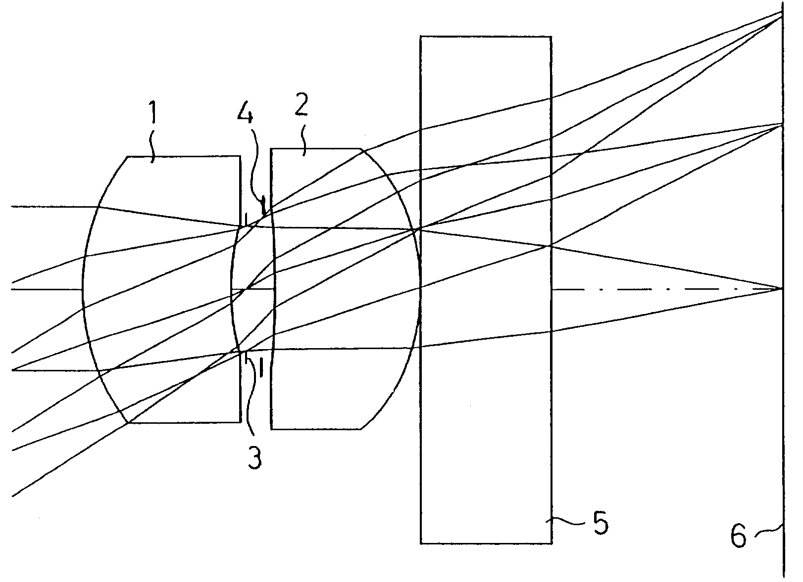
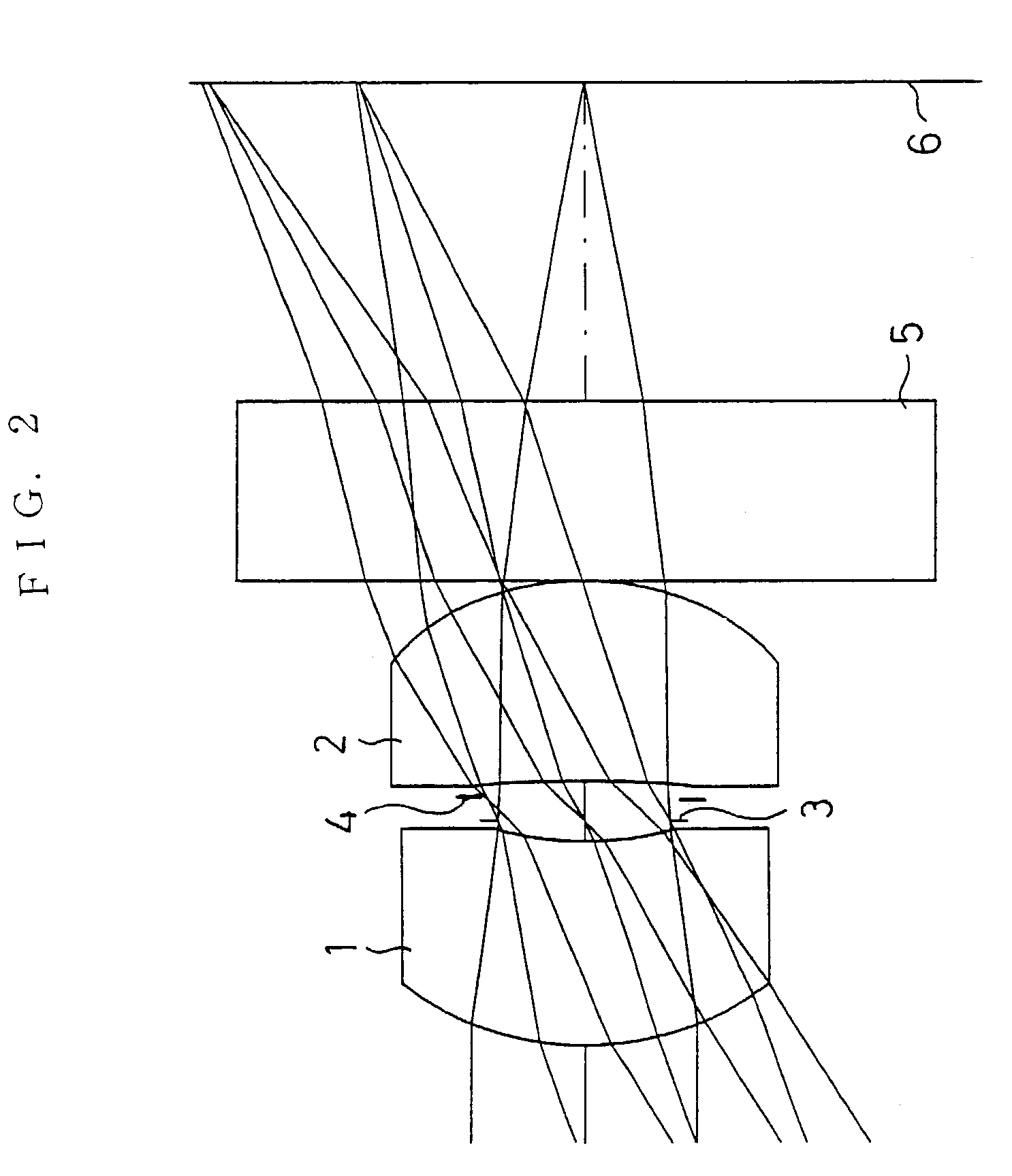
[0053]FIG. 2 shows Example 1 of the present invention. In Example 1, as in the image pickup lens of the first embodiment shown in FIG. 1, the diaphragm 3 was provided in the vicinity of the second face of the first lens 1 and the light quantity control plate 4 was provided between the diaphragm 3 and the first face of the second lens 2.

[0054]The image pickup lens of Example 1 was set under the following condition:

[0055]f1=3.09 mm, f1=9.35 mm, f2=3.07 mm, F No=2.8

[0056]

Radius rofRefractiveAbbe ConstantFaceCurvatureDistance dIndex ndνd(1)First face of1.5381.00001.5256.0First lens(2)Second face of1.7390.0500First lens(3)Diaphragm0.0000.1500(4)Light quantity0.0000.1000control plate(5)First face of−10.0001.00001.5256.0Second lens(6)Second face of−1.4350.0000Second lens(7)First face of0.00000.90001.51664.0Cover glass(8)Second face of0.0001.5673Cover glass(9)Image pickup0.000surface

[0057]

Aspherical FactorFaceKa4a6a8a1010.00e+00  9.47e−03  1.51e−02−1.79e−02  1.84e−0223.88e+00−1.10e−02  9.20...

example 2

[0060]FIG. 4 shows Example 2 of the present invention. In Example 2, as in the image pickup lens of the first embodiment shown in FIG. 1, the diaphragm 3 was provided in the vicinity of the second face of the first lens 1.

[0061]The image pickup lens of Example 2 was set under the following condition:

[0062]f1=3.09 mm, f1=6.96 mm, f2=3.20 mm, F No=2.8

[0063]

Radius rofRefractiveAbbe ConstantFaceCurvatureDistance dIndex ndνd(1)First face of1.4051.10001.5256.0First lens(2)Second face of1.6670.0500First lens(3)Diaphragm0.0000.2500(4)First face of−20.0001.10001.5256.0Second lens(5)Second face of−1.5800.0000Second lens(6)First face of0.00000.90001.51664.0Cover glass(7)Second face of0.0001.2489Cover glass(8)Image pickup0.000surface

[0064]

Aspherical FactorFaceKa4a6a8a1010.00e+00  2.91e−03  2.17e−02−2.32e−02  1.88e−0226.61e+00−8.36e−02−3.57e−01  0.00e+00  0.00e+0040.00e+00−9.21e−02−2.82e−02−2.25e−01  0.00e+0059.12e−01  5.96e−03−1.69e−02  1.88e−02−1.57e−02

[0065]Under such condition, f1 / f2=2.18 wa...

example 3

[0067]FIG. 6 shows Example 3 of the present invention. In Example 3, as in the image pickup lens of the first embodiment shown in FIG. 1, the diaphragm 3 was provided in the vicinity of the second face of the first lens 1 and the light quantity control plate 4 was provided between the diaphragm 3 and the first face of the second lens 2.

[0068]The image pickup lens of Example 3 was set under the following condition:

[0069]f1=3.00 mm, f1=4.55 mm, f2=3.82 mm, F No=2.8

[0070]

Radius rofRefractiveAbbe ConstantFaceCurvatureDistance dIndex ndνd(1)First face of1.4181.15001.5456.0First lens(2)Second face of2.3810.0500First lens(3)Diaphragm0.0000.0500(4)Light quantity0.0000.2000control plate(5)First face of−4.8781.15001.5456.0Second lens(6)Second face of−1.5750.0000Second lens(7)First face of0.00000.70001.51664.0Cover glass(8)Second face of0.0001.1544Cover glass(9)Image pickup0.000surface

[0071]

Aspherical FactorFaceKa4a6a8a1010.00e+00  8.06e−03−2.65e−03  1.51e−02  0.00e+0021.70e+00  3.19e−02−1.47e...


PUM


Abstract

Provided is an image pickup lens, in which the optical characteristic can be improved and, further, the productivity can be improved through increasing the telecentricity by keeping the distance between the exit pupil and the sensor and effectively correcting the coma aberration and the distortion aberration. A first lens which is a meniscus lens having a positive power with its convex face facing an object side, a diaphragm, and a second lens which is a lens having a positive power with a strong convex face facing an image pickup surface side are provided in order from the object side. The first lens and the second lens are to satisfy the condition represented by following expressions:4×f2≧f1≧f2  (1)1.5×f1≧f2≧0.9×f1  (2)where,f1: focal length of the whole lens systemf1: focal length of the first lensf2: focal length of the second lens.

Description

BACKGROUND OF THE INVENTION[0001]1. Field of the Invention[0002]The present invention relates to an image pickup lens and particularly, to an image pickup lens comprising two lenses which can be reduced in size and weight while achieving a wider angle of view to be used for an image pickup device utilizing an image pickup element such as a CCD, a CMOS or the like to be mounted on a portable computer, a visual telephone, a cellular phone and the like.[0003]2. Description of the Related Art[0004]Recently, there is a remarkable development in the multimedia industry. For example, there has been an increasing demand for a camera utilizing an image pickup element such as a CCD, a CMOS or the like to be mounted on a portable computer, a visual telephone, a cellular phone and the like. Such camera needs to be mounted on a limited space. Thus, it is desirable that the camera be small in size and light in weight.[0005]Accordingly, an image pickup lens used for such CCD camera is also require...

Claims


Application Information

Patent Timeline
Patent Type & Authority Patents(United States)
IPC IPC(8): G02B13/18G02B9/08G02B9/04G02B13/00
CPCG02B9/04G02B13/003
Inventor SAITO, TOMOHIRO
Owner ENPLAS CORP
Why Eureka
Eureka Blog
Learn More