

Disc drive actuator assembly with trunk flexible printed circuit board damping configuration
- Summary
- Abstract
- Description
- Claims
- Application Information
AI Technical Summary
Benefits of technology
Problems solved by technology
Method used
Image

Examples
example
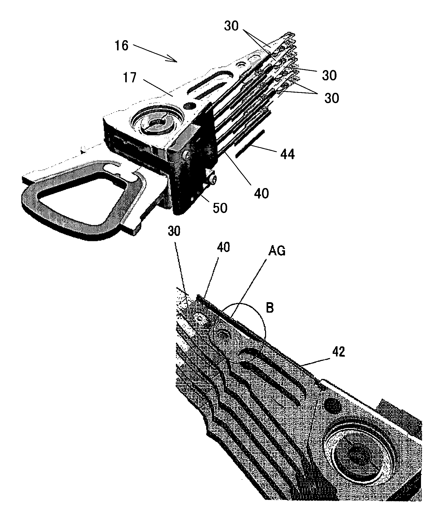
[0063]When the constraint layer 44 is made of polyimide having a thickness of 50 μm and the elastic member 42 is made of a viscoelastic material in the structure shown in FIG. 4, the gain reduces at frequency of about 8,000 Hz or higher, as shown in FIG. 17. In FIG. 17, a red line corresponds to the prior art structure (i.e., the structure shown in FIG. 4 without the constraint layer 44) and a blue line corresponds to the inventive structure shown in FIG. 4. As discussed, the instant embodiment may sets the necessary damping based on the gain reduced at the target specific oscillation frequency, e.g., about 8,000 Hz or higher.
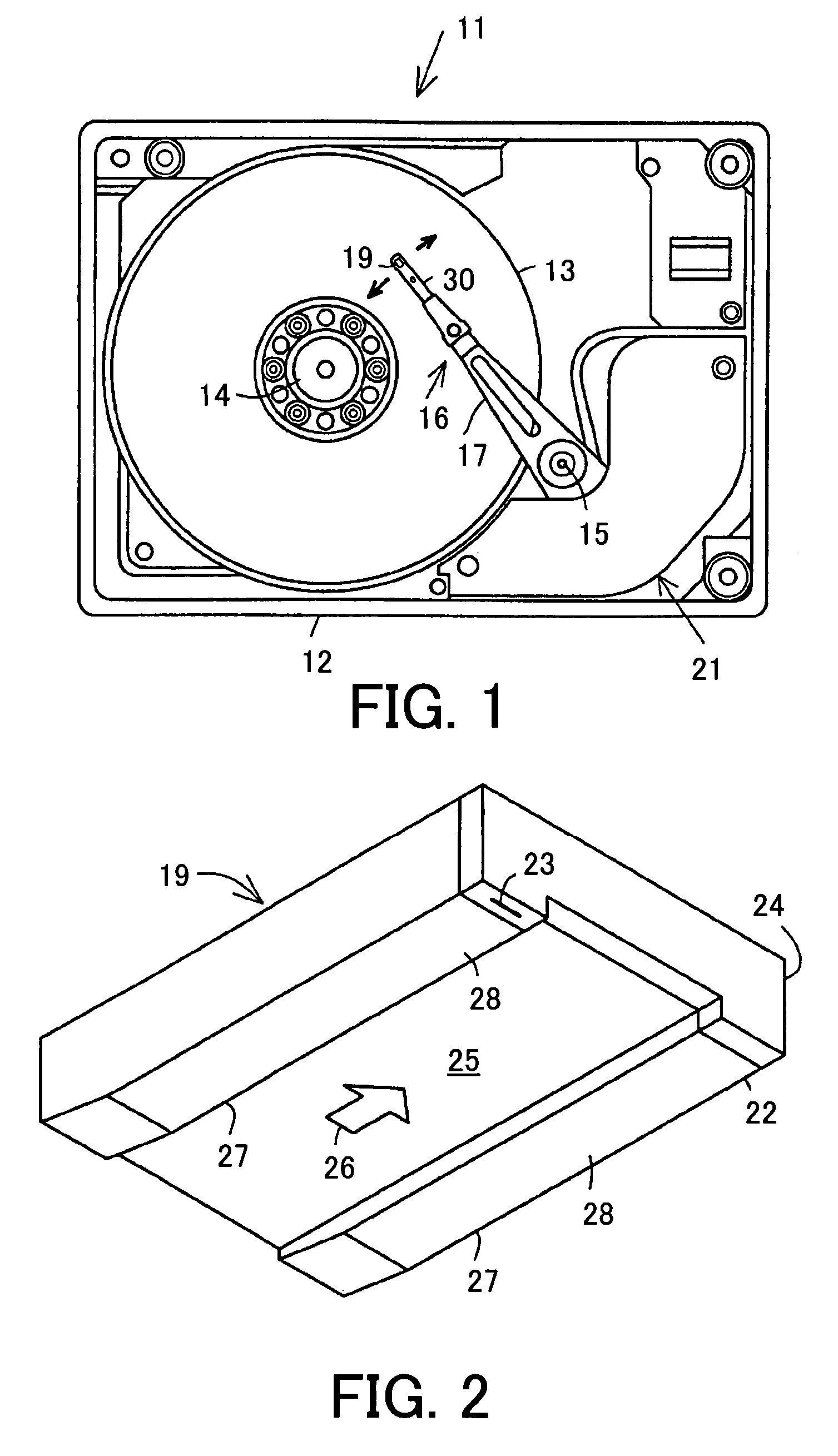
[0064]The control part 71 then controls the actuator 21 and rotates the carriage 16 around the support shaft 15 for head 23's seek for a target track on the disc 13. The instant embodiment thus uses a swing arm type in which the slider 19 draws an arc locus around the support shaft 15, but the present invention is applicable to a linear type in which the slider...
PUM
 Abstract
Description
Claims
Application Information