Supercharge Your Innovation With Domain-Expert AI Agents!

Optical disk identification circuit

a technology of optical disks and identification circuits, applied in the direction of digital signal error detection/correction, instruments, recording signal processing, etc., can solve the problems of unstable disk determination operation, unstable optical disk determination, unstable, etc., and achieve the effect of improving the stability of peak (pulse signal) detection

Active Publication Date: 2006-11-21
TEXAS INSTR INC
View PDF10 Cites 3 Cited by
  • Summary
  • Abstract
  • Description
  • Claims
  • Application Information

AI Technical Summary

Benefits of technology

The present invention offers an optical disk determination circuit that can detect the kind of optical disk by measuring the distance from the light beam irradiation plane to the data recording layer. This circuit includes an input terminal, a clamp circuit, a comparator circuit, and a calculation circuit. Additionally, a filter circuit and an amplifier circuit can be included. The circuit can also determine if the optical disk is a CD or a DVD based on the distance measurement. The technical effect of this invention is to provide a reliable and accurate method for identifying different types of optical disks.

Problems solved by technology

Therefore, sometimes the effects of noise, etc. cause errors to be generated when detecting this extremely small peak value, and the disk determination operation becomes unstable.
Specifically, in a system that sets up a threshold level for detecting peaks using a maximum peak level and minimum peak level retained by peak holder circuits, there is the problem that it is highly possible that an optical disk determination error will be made because noise is prone to cause operational errors during periods in which no peak is input.
Moreover, the timing whereby the detection signal Sp becomes the logical value “1” will become unstable, and the stability of the optical disk determination operation will be lost because the capacitance value of the capacitor C2 and the input impedance of the amplifier 13 will vary the size of this level fluctuation.

Method used


Image

  • Optical disk identification circuit
  • Optical disk identification circuit
  • Optical disk identification circuit

Examples


Embodiment Construction

[0040]A form of embodying the present invention will be explained below by referring to FIGS. 1 through 5.

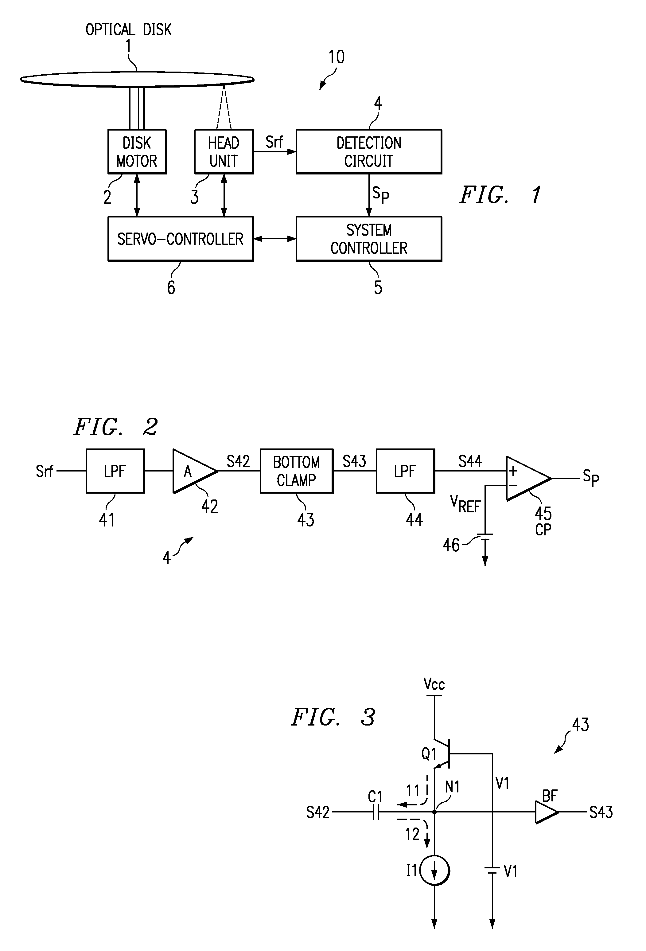
[0041]FIG. 1 is a schematic block diagram indicating one form of embodying an optical disk determination device 10 relating to the present invention.

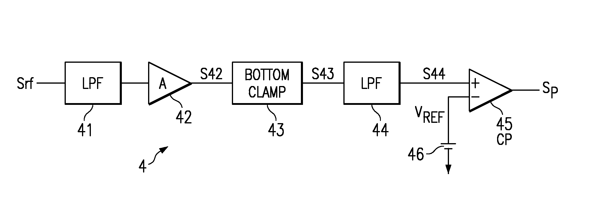
[0042]In FIG. 1, the code 1 indicates an optical disk; the code 2 is a disk motor; the code 3 is a head unit; the code 4 is a detection circuit; the code 5 is a system controller; and the code 6 is a servo-controller.

[0043]The disk motor 2 supports the loaded optical disk 1 such as a CD or DVD, and rotates the optical disk 1 at a rotational velocity controlled by the servo-controller 6.

[0044]The head unit 3 is provided with: an oscillator of laser light to be irradiated on various optical disks 1; an optical system that irradiates and receives laser light; an optical detector that detects light received by the optical system and converts it to electrical signals; a received light signal amplifier that amplifies signals from the ligh...


PUM

PropertyMeasurementUnit
thicknessaaaaaaaaaa
thicknessaaaaaaaaaa
distanceaaaaaaaaaa

Abstract

The present invention offers an optical disk determination circuit that can improve the stability of the operation to detect the peak (pulse signal) of the received light signal, and that can improve the stability of the optical disk determination operation. When determining the type of optical disk corresponding to the depth from the surface of the plane on which a light beam is irradiated to the data recording layer, light is irradiated while varying the focal position of the light beam at a constant velocity in one direction of the depth direction from the surface of the optical disk. The bottom level of the received light signal corresponding to the intensity of this reflected light is clamped at a specified level by the bottom clamp circuit 43. The received light signal with the bottom level clamped is compared with a specified reference voltage Vref by the comparator 45, and the received light signal peak (pulse signal) is detected corresponding to the results of this comparison. The type of optical disk is determined by measuring the difference in this peak (pulse signal) detection time.

Description

FIELD OF THE INVENTION[0001]The present invention is related to an optical disk determination circuit that is used in order to determine the type of optical disk, such as a CD or DVD, in which there are differences in the depth from the surface of the disk plane, which is irradiated with laser light to the data recording layer.BACKGROUND OF THE INVENTION[0002]Optical disk playback devices, for example, DVD (Digital Versatile Disk) players, have been spreading rapidly in recent years, and are being equipped with generalized functions that can play back other types of optical disks, specifically, functions that can play back CDs (Compact Disks), which have already become widespread. This kind of optical disk playback device is normally equipped with a function to determine the type of optical disk that is loaded in the equipment, and suitable playback processing or recording processing is conducted corresponding to the type determined.[0003]In general optical disks, a long narrow conv...

Claims


Application Information

Patent Timeline
Patent Type & Authority Patents(United States)
IPC IPC(8): G11B7/00G11B19/12G11B7/004G11B7/085
CPCG11B7/08511G11B2007/0006
Inventor YAMANOI, KOYUYAMAUCHI, TOSHIOMURATA, HIRONOBU
Owner TEXAS INSTR INC
Features
  • R&D
  • Intellectual Property
  • Life Sciences
  • Materials
  • Tech Scout
  • Unparalleled Data Quality
  • Higher Quality Content
  • 60% Fewer Hallucinations
Learn More