
Precision soft-touch gripping mechanism for flat objects

a flat object and soft touch technology, applied in the field of material handling equipment, can solve the problems of confusion, not solving the contamination problem, adding unnecessary complexity to the equipment design, etc., and achieve the effect of high reliability

Inactive Publication Date: 2006-11-28
MULTIMETRIXS
View PDF13 Cites 59 Cited by
  • Summary
  • Abstract
  • Description
  • Claims
  • Application Information

AI Technical Summary

Benefits of technology

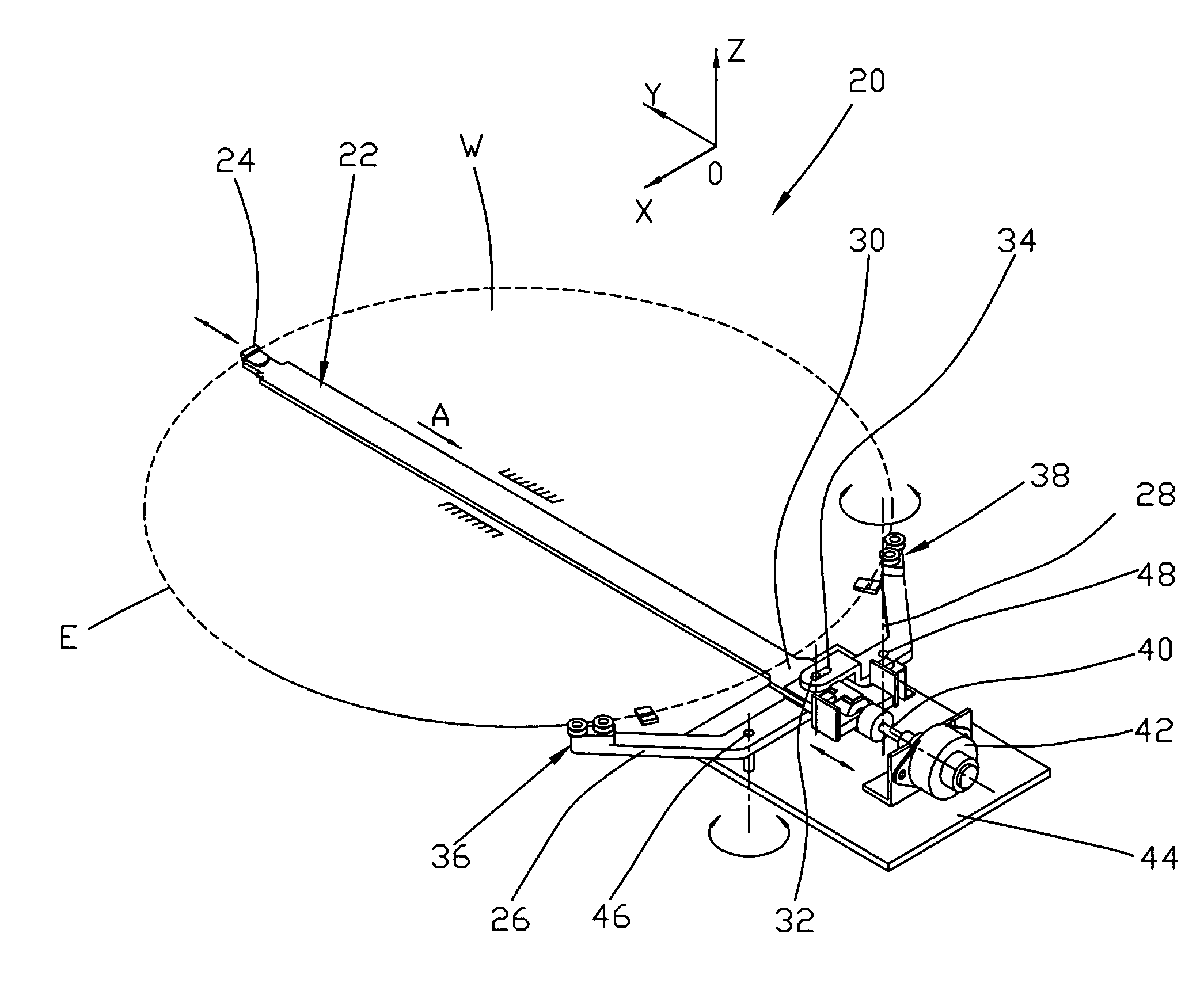
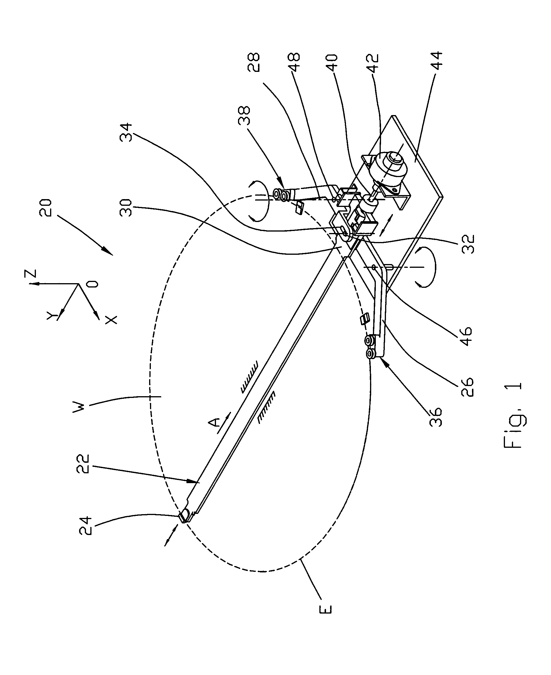
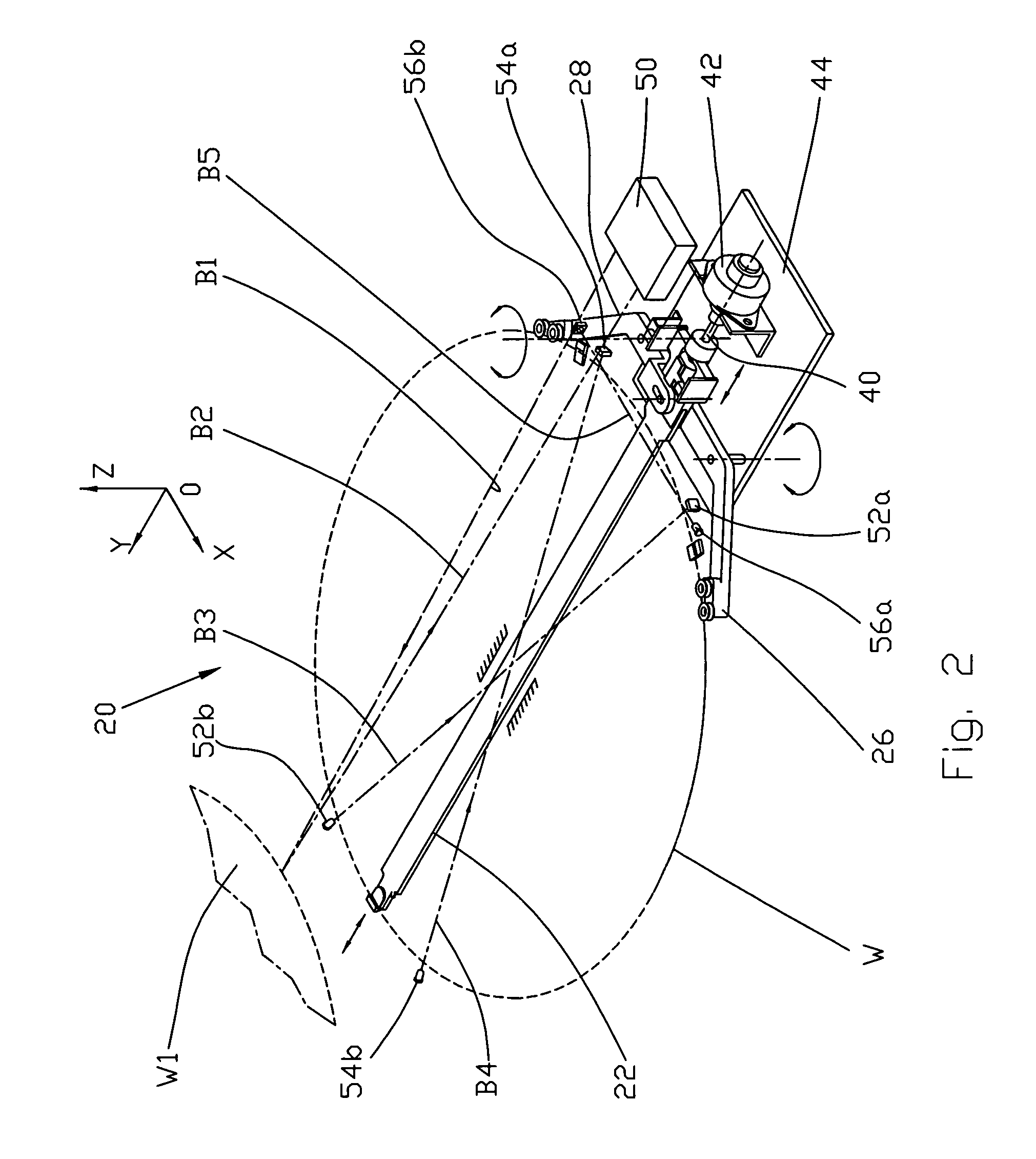
"The invention is a precision soft-touch gripping mechanism for a robot arm that can hold and position wafers accurately. It has a thin mounting plate that can fit into a wafer-holding slot of a cassette, and a stepper motor that controls the gripping force through a force control unit and a bar that slides in a central longitudinal slot of the plate. The mechanism is equipped with three sets of sensors: a mapping sensor, wafer position sensors, and sensors for measuring and controlling the gripping force. It provides an extremely accurate positioning of the wafer and a precisely controlled gripping force with a soft touch. Different embodiments have different arrangements of gripping rollers and mechanisms for control of gripping force speed and acceleration."

Problems solved by technology

This to some extent helped to reduce breakage, but did not solve the contamination problem.
However, these standards helped reduce, but did not eliminate, the confusion involved in the selection and application of robotic wafer handling.
Another compromise is the need to design semiconductormanufacturing equipment suitable for accepting a large variety of wafer sizes.
This adds unnecessary complexity to equipment design.
Recent transfer to 300-mm wafers, evolved new problems associated with much higher cost of a single wafer (up to several thousand dollars as compared with several hundred dollars for 200 mm wafers) and thus required higher accuracy and reliability of the wafer handling equipment.
Furthermore, transition to 300 mm wafers made the use of low vacuum unsuitableforholding and handling the wafers.
Another reason is that vacuum holders are not reliable for handling wafers of heavy weight.
Thus, the conventional vacuum end effectors appeared to be unsuitable for handling expensive, heavy, and hard-to-grip wafers of 300 mm diameter.
Using mechanical measurements or preliminary mapping procedures of location of the wafer in a cassette for precise positioning of the gripper relatively to the grasping points is a time consuming procedure that is difficult to perform in real conditions of the variety of wafer stages at wafer handling robotic lines.
However, such a robot arm is three-dimensional and is not applicable for handling thin flat objects, such as semiconductor wafers, located in a deep narrow slots of a multistack cassette of the type used for storing the wafers.
A disadvantage of the wafer handling system of Hollbrooks consists in that this apparatus does not provide control of gripping speed at different stages of the gripping cycle.
Another disadvantage of the Hollbrooks system consists in that this system does not provide decrease in gripping pressure when the gripper approaches the edge of the wafer with acceleration.
The solution proposed by Bartunek et al. to install the wafer mapping sensor on the wrist end hand or on one side of gripper does not solve the problem of detecting the wafer before gripping or during regular mapping process.
But even if the precise position of the front edge of the wafer is known, there is no guarantee that the position of the backside of the wafer is related to the same plane as the front edge.
In the meantime any inclination and tilted position of the wafer in a cassette might lead to wafer breakage during the gripping process.
A disadvantage of the device of U.S. Pat. No. 6,256,555 consists in that this device does not allow to divide the gripping process into several stages with different controllable speeds.
The decrease in speed, however, reduces productivity of the gripper's operation.
A parallel vice-like grip is generated, but there are no means of detecting the real orientation of the wafer relative to the gripper.
More problems related to a limited load that robot arm is able to carry and the amount of wires that can deliver the control and sensing signals to a robot controller.
Thus none of the existing robot-arm end effectors is suitable for grasping and moving semiconductor wafers with high precision and grasping force controlled so as to provide soft touch without loss in productivity of the gripping device.

Method used


Image

  • Precision soft-touch gripping mechanism for flat objects
  • Precision soft-touch gripping mechanism for flat objects
  • Precision soft-touch gripping mechanism for flat objects

Examples


embodiment

of FIG. 14

[0074]Since the end effector 20F of this embodiment is similar to the end effectors of the previous embodiments, a detailed description of its operation is omitted. The device of FIG. 14 differs from the embodiments of FIGS. 5 and 13 in that when the stepper motor 42F begin to operate for initiation of the gripping motion, extreme or outer rollers of each pair, i.e., rollers 36aF and 38aF, are shifted under effect of a respective strain-gauged leaf springs 68F and 70F radially inwardly towards the center of the wafer W, the rollers 36aF and 38aF come into contact with the edge EW first, i.e., prior to contact of the rollers 36bF and 38bF with the same edge. At the moment of contact of the rollers 36aF and 38bF with the wafer edge EW the strain gauges of the springs 68F and 70F send commands to the stepper motor 42F for immediate decrease in the speed of gripping, so that further movement of the gripping posts till the moment of contact of the rollers 36bF and 38bF occurs w...


PUM


Abstract

A precision soft-touch gripping mechanism has a mounting plate attached to a robot arm. The plate supports a stepper motor. The output shaft of the stepper motor is connected through a spring to an elongated finger that slides in a central longitudinal slot of the plate and supports a first wafer gripping post, while on the end opposite to the first wafer gripping post the mounting plate pivotally supports two L-shaped fingers with a second and third wafer gripping posts on their respective ends. The mounting plate in combination with the first sliding finger and two pivotal fingers forms the end effector of the robot arm which is thin enough for insertion into a wafer-holding slot of a wafer cassette. The end effector is equipped with a mapping sensor for detecting the presence or absence of the preceding wafer, wafer position sensors for determining positions of the wafer with respect to the end effector, and force sensors for controlling the wafer gripping force. Several embodiments relate to different arrangements of gripping rollers and mechanisms for control of the gripping force and speed of gripping required for gripping the wafer with a soft and reliable touch.

Description

FIELD OF THE INVENTION[0001]The present invention relates to the field of material handling equipment, in particular to mechanisms used in semiconductor production, disk-drive manufacturing industries and the like for precision gripping, transportation and positioning delicate, thin and highly accurate flat objects such as semiconductor wafers, hard disks, etc.BACKGROUND OF THE INVENTION[0002]One of the major methods used at the present time in the semiconductor industry for grasping, holding, moving, and positioning of semiconductor wafers is the use of a mechanical hand of a robot equipped with a vacuum chuck.[0003]From the beginnings of the semiconductor industry to the late 1980s, wafers were handled manually and later by rubber-band conveyors and cassette elevators. The first standards for wafer of 2″, 4″, 6″ diameters and appropriate cassette dimensions allowed to develop simple wafer handling mechanisms and standardize their designs. The early forms of automated handling cont...

Claims


Application Information

Patent Timeline
Patent Type & Authority Patents(United States)
IPC IPC(8): B66C1/44B65G49/07B25J9/16
CPCB25J9/1633G05B2219/37003G05B2219/39505Y10S414/141
Inventor KESIL, BORISMARGULIS, DAVIDGERSHENZON, ELIK
Owner MULTIMETRIXS
Learn More