Liquid crystal display driving scaler capable of reducing electromagnetic interference

a technology of electromagnetic interference and driving scaler, which is applied in the direction of static indicating devices, instruments, cathode-ray tube indicators, etc., can solve the problems of reducing emi, display devices such as large-sized monitors or lcds, etc., and pcs operating at high clock frequencies are susceptible to serious electromagnetic interference problems

Inactive Publication Date: 2006-11-28
SAMSUNG ELECTRONICS CO LTD
View PDF19 Cites 19 Cited by
  • Summary
  • Abstract
  • Description
  • Claims
  • Application Information

AI Technical Summary

Benefits of technology

[0046]Preferably, a spread spectrum effect is obtained when the system clock signal is converted into the predivider signal through frequency modulation.
[0

Problems solved by technology

High-speed personal computers (PCs), which operate at high clock frequencies, are susceptible to a serious problem of electromagnetic interference (EMI).
Display devices, such as large-sized monitors or LCDs, also have the same problem as the high-speed PCs because of a high pixel clock frequency.
However, EMI is reduced through repetitive trials and failures, and thus increases in the material and manufacturing costs and the time taken to develop a product are inevitable.
An LCD monitor having SXGA resolution or higher also requires the above-described spread spectrum modulation technique using a spread spectrum clock generator because an LCD monitor having a high resolution uses a high-frequency system clock of about 100 MHz, which means that a user of the LCD monitor is susceptible to exposure to strong electromagnetic waves at such a high frequency level.
However, since the above-mentioned conventional spread spectrum modulation methods use a PLL in a spread spectrum clock generator and a PLL included in a scaler, a mismatch in frequencies between the two PLLs is more likely to occur.
In other words, due to a mismatch

Method used


Image

  • Liquid crystal display driving scaler capable of reducing electromagnetic interference
  • Liquid crystal display driving scaler capable of reducing electromagnetic interference
  • Liquid crystal display driving scaler capable of reducing electromagnetic interference

Examples


Embodiment Construction

[0056]Hereinafter, the present invention will be described in greater detail with reference to the accompanying drawings in which preferred embodiments of the present invention are shown. In the drawings, the same reference numerals represent the same elements.

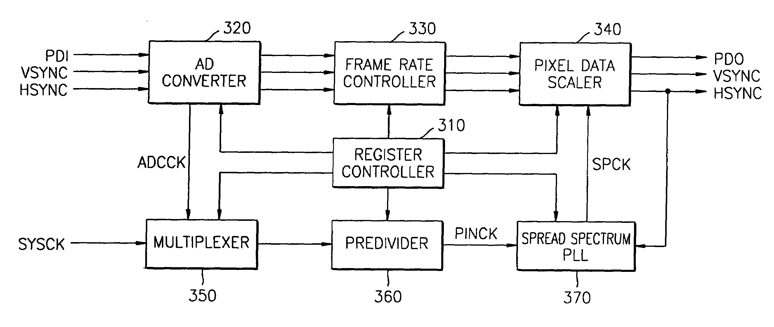
[0057]FIG. 3 is a block diagram of a scaler for driving a liquid crystal display (LCD) according to a preferred embodiment of the present invention. Referring to FIG. 3, the scaler includes a register controller 310, an analog-to-digital (AD) converter 320, a frame rate controller 330, a pixel data scaler 340, a multiplexer 350, a predivider 360, and a spread spectrum phase locked loop (PLL) 370.

[0058]The register controller 310 stores predetermined control information in a register and performs general control operations. Here, the predetermined control information stored in the register includes the division rate of the predivider 360 and of a main divider 376 (see FIG. 4) of the spread spectrum PLL 370, modulation frequency...


PUM


Abstract

An LCD driving scaler capable of reducing electromagnetic interference employs a spread spectrum phase locked loop (PLL) in which a multi-phase voltage controlled oscillator oscillates and outputs a scaler pixel clock signal and a plurality of oscillation signals of different phases. A spread spectrum processor counts clock periods of a reference pixel clock signal when a horizontal synchronization signal having an adjusted frame rate is activated, and sequentially outputs the plurality of oscillation signals in response to a decoding signal. The plurality of oscillation signals are output to a main divider, which generates the main divider signal by dividing the frequencies of the plurality of oscillation signals. A main divider signal is input into a phase frequency detector, which detects a phase difference between the predivider signal and the main divider signal and outputs the phase difference signal so that the frequency of the scaler pixel clock signal repeatedly varies.

Description

[0001]This application claims the priority of Korean Patent Application No. 2002-76698, filed Dec. 4, 2002, in the Korean Intellectual Property Office, the disclosure of which is incorporated herein in its entirety by reference.BACKGROUND OF THE INVENTION [0002]1. Field of the Invention[0003]The present invention relates to a liquid crystal display (LCD), and more particularly, to an LCD driving scaler which is capable of reducing electromagnetic interference.[0004]2. Description of the Related Art[0005]High-speed personal computers (PCs), which operate at high clock frequencies, are susceptible to a serious problem of electromagnetic interference (EMI). Display devices, such as large-sized monitors or LCDs, also have the same problem as the high-speed PCs because of a high pixel clock frequency. For this reason, a variety of research have been carried out with respect to methods for reducing EMI.[0006]In order to reduce EMI, a metal shielding technique can be applied. Alternatively...

Claims


Application Information

Patent Timeline
IPC IPC(8): G09G3/36
CPCG09G5/18G09G2330/06G09G2340/0435G09G2340/0421G09G2340/0414G09G3/36
Inventor KIM, HO-YOUNGKIM, YONG-SUB
Owner SAMSUNG ELECTRONICS CO LTD
Why Eureka
Try Eureka