

Low jitter digital frequency synthesizer and control thereof
a digital frequency synthesizer and low jitter technology, applied in the field of frequency synthesizers, can solve the problems of analog circuits being susceptible to noise generated by digital circuits, too slow desired output oscillation, and too fast desired output oscillation
- Summary
- Abstract
- Description
- Claims
- Application Information
AI Technical Summary
Benefits of technology
Problems solved by technology
Method used
Image

Examples
Embodiment Construction
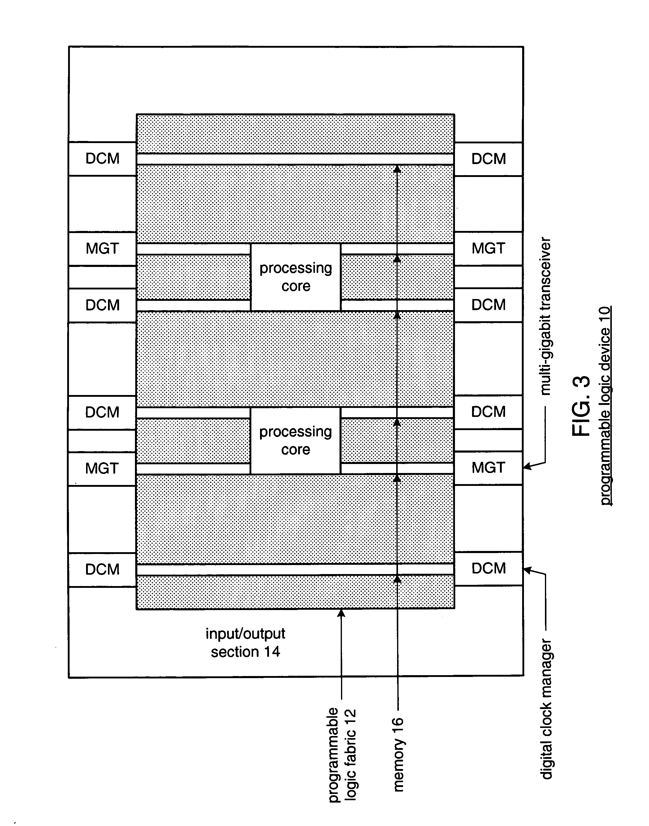
[0027]FIG. 3 is a schematic block diagram of a programmable logic device 10 that includes programmable logic fabric 12, an input / output section 14, and memory 16. The programmable logic fabric 12 may include one or more processing cores and programmable logic circuitry. Such programmable logic circuitry may include programmable logic arrays (PLA), programmable array logic (PAL) devices, erasable programmable logic devices (EPLD) and / or programmable gate arrays (PGA). The memory 16 may be block random access memory (BRAM). The input / output section 14 may include a plurality of digital clock managers (DCM) and a plurality of multi-gigabit transceivers (MGT).
[0028]The digital clock managers (DCM) provide various clock signals to the programmable logic fabric 12 and may further provide clock signals to the multi-gigabit transceivers. The multi-gigabit transceivers provide digital interfaces for the programmable logic fabric 12 to components external to the programmable logic device 10. ...
PUM
 Abstract
Description
Claims
Application Information