
Recoil and muzzle blast dissipator

a technology of reloading and discharging, which is applied in the direction of muzzle attachment, weapon components, weapons, etc., can solve the problems of collarbone and shoulder, irremediable effects, and never eliminating

Active Publication Date: 2006-12-05
BENDER TERRENCE D
View PDF17 Cites 37 Cited by
  • Summary
  • Abstract
  • Description
  • Claims
  • Application Information

AI Technical Summary

Benefits of technology

[0014]It is an objective of the subject invention to redirect the propellant gases ejected from the gun barrel muzzle of large caliber rifles to produce reaction vectored forces using the same propellant gas to counteract the recoil inertial forces of the accelerated bullet without developing an uncomfortable or unsettling shockwave at the shooter's position or the spotter's side-position.
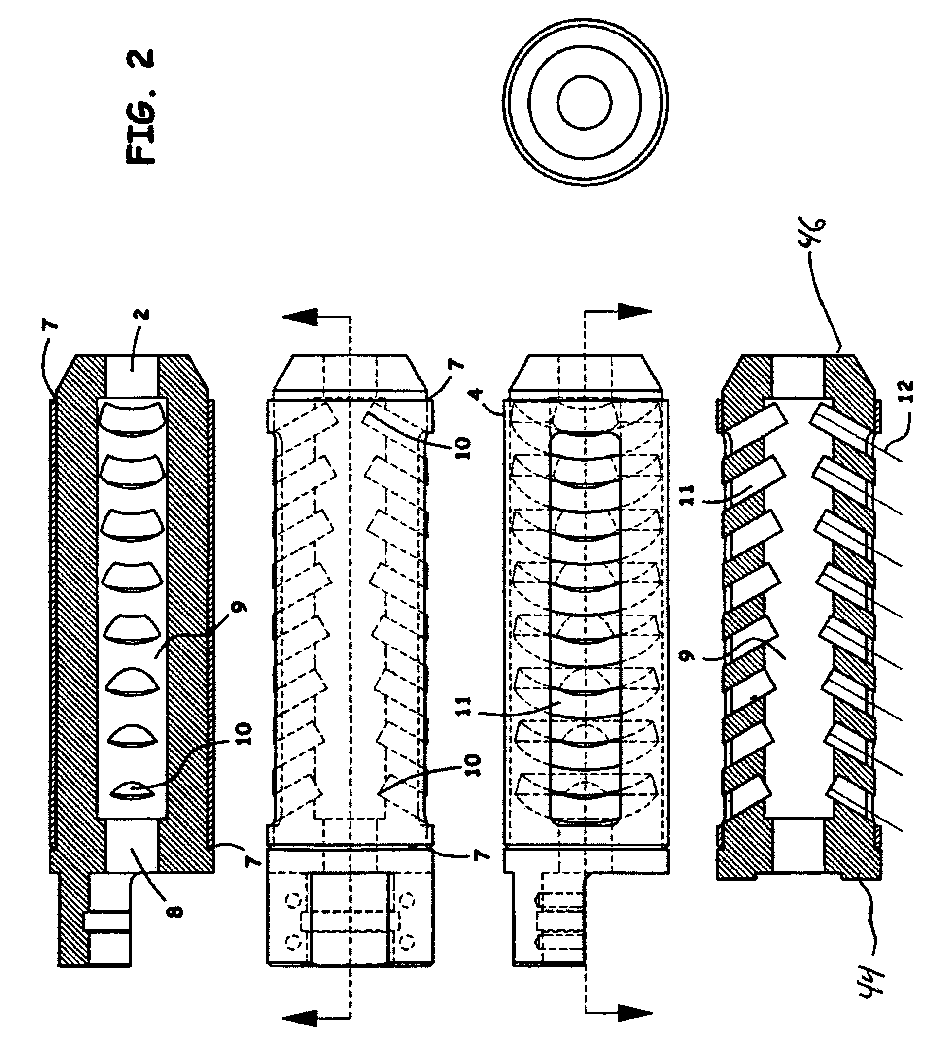
[0020]A further feature of several embodiments of the invention is the effect that the vertical slots may have on the supersonic gas exiting through the laterally mirrored slot pairs. The gas entering the plenum(s) may be traveling supersonically forward. The pressure may be relieved at the sides through the exhaust ports. The gas must change direction and in doing so it also exchanges momentum with the brake and thus with the gun. The gas may slam into a forward face of the vertically cut vent slots on the outer side of the brake port. When it does so, the gas stream may be forced to fan out and flatten from a narrow flow stream equal in size to the port orifice. This cools the flow with an effect discussed below. This fanned out jet of cooling hot gas leaves the slot areas. This cooling effect is enhanced by the turbulence generated by the irregularly shaped orifice holes. Across the width of the slot, progressing from the forward to the rearward sides, there develops a velocity gradient across the gas flow as the velocity is seen to go from a high value to a lower value, which tends to break up the coherence of any exhaust gas shock wave coming through the orifice.
[0022]An exterior plenum may function to further slow down the gas by partial containment and to disrupt the streamed flow of the exhausting gases as well as to direct them rearward for the recoil thrust cancellation effect. Recall that the forward-most vertical slot wall fans out the gas exiting the interior plenums. The upper and lower extremities of the flow fan may be intersected and disrupted by the confining walls of the tube on the top and bottom sides of the tube slot. This reshapes the flow pattern of the gas immediately exiting the vertical slots from a simple fan to a U-shaped pattern at the exit interface, where the base of the U-shape is in a forward position, flowing off of the forward-most face of the slot and streams forming the legs of the U-shape being the concentrated flow patterns at the top and the bottom. The effect is to further mix the flow shedding from the vertical slots and the tube slot, creating a concentrated disrupted flow stream that is characterized by varying velocity gradients in all reference planes.
[0023]The shape and turbulent mixing characteristics of the flow emanating from each exterior external brake port is a function of the flow velocity and volume of gas passing through the interior plenums. In general, as stated above, the resultant force generated by the exhausting gas tends to be equal for each vent, yet, because the velocities are different due to the position of the plenum orifices with respect to one another in the rearward, or forward sense, and the pressure drop of the propellant gas, the further the gas has traveled beyond the barrel muzzle, the flow pattern will appear different. The cumulative effect of all of the ports exhausting gas at nearly the same time but at different velocities is that no coherent shock wave front can form. Contrast this with the shock wave developed by the best conventional muzzle brakes and the advantages of this novel design will be more apparent. Any coalescence of individual shock fronts developing and adding is obviated by the generation of multiple turbulent eddies within all flows. The turbulence and time spent in disruptive energy dissipating flow patterns as the plenums fill, then empty, and quickly drop in pressure after the bullet ejection event, tends to cool the hot gases more quickly than if the flows were less disrupted. The cooling has the effect of shrinking the exhausted hot gas faster, further reducing shock waves that are either perceived as sound, or felt on the shooter's or spotter's body.
[0025]The resulting inventive design is a muzzle brake for large caliber rifles that is comprised of two easily machined and welded metal components that allows for the quick and effective exhaustion of large volumes of propellant gas through variously sized, arranged, and force vectoring ports, which object has not been addressed by the prior art. This novel inventive design maximizes the generation of recoil canceling thrust vectoring forces, minimizes the shock wave effects exhibited in an amelioration of the sound report, and minimizes the lofting of ground-borne debris into the surrounding air at the shooter's position, all of which enhances the shooter's comfort and his ability to stay sighted on the target, or reacquire the target, for faster successive firings.

Problems solved by technology

However well this design improves the controllability of recoil effects, it can never eliminate them.
The rifle tends to stay on target, but the abuse suffered by the collarbone and shoulder can have irremediable outcomes as the recoil energy formerly absorbed by the shooter in the slowly rocking motion of the upper torso during standing or sitting is now absorbed more directly without the benefit of a large movement to spread the energy out over time.
The most adverse effect of recoil is loss of target acquisition during the shot and the added amount of time to reacquire the target prior to firing the next shot.
However, the prior art does not address management of very large volumes of propellant gases issued from large caliber rifles.
However, this occurs at the expense of the shooter and the spotter situated nearby at the shooter's flank, both of which experience the back-blast shockwave as a punctuated and very loud noise, which of itself, can upset target reacquisition, and additionally may kick up debris lying on the ground nearby that can obscure the target area or give away the shooter's position.

Method used


Image

  • Recoil and muzzle blast dissipator
  • Recoil and muzzle blast dissipator
  • Recoil and muzzle blast dissipator

Examples


Embodiment Construction

[0039]While this invention may be embodied in many different forms, there are described in detail herein specific preferred embodiments of the invention. This description is an exemplification of the principles of the invention and is not intended to limit the invention to the particular embodiments illustrated.

[0040]For the purposes of this disclosure, like reference numerals in the figures shall refer to like features unless otherwise indicated.

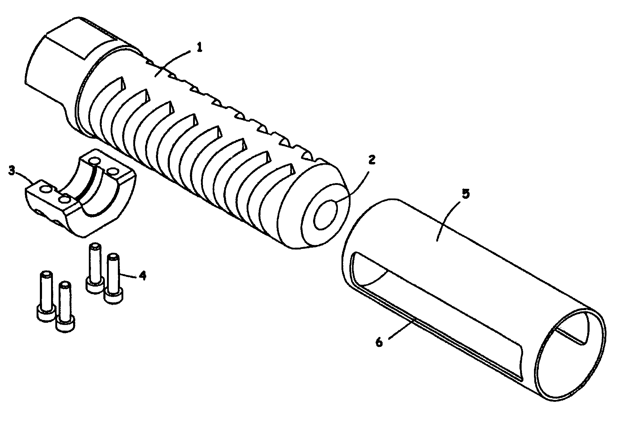
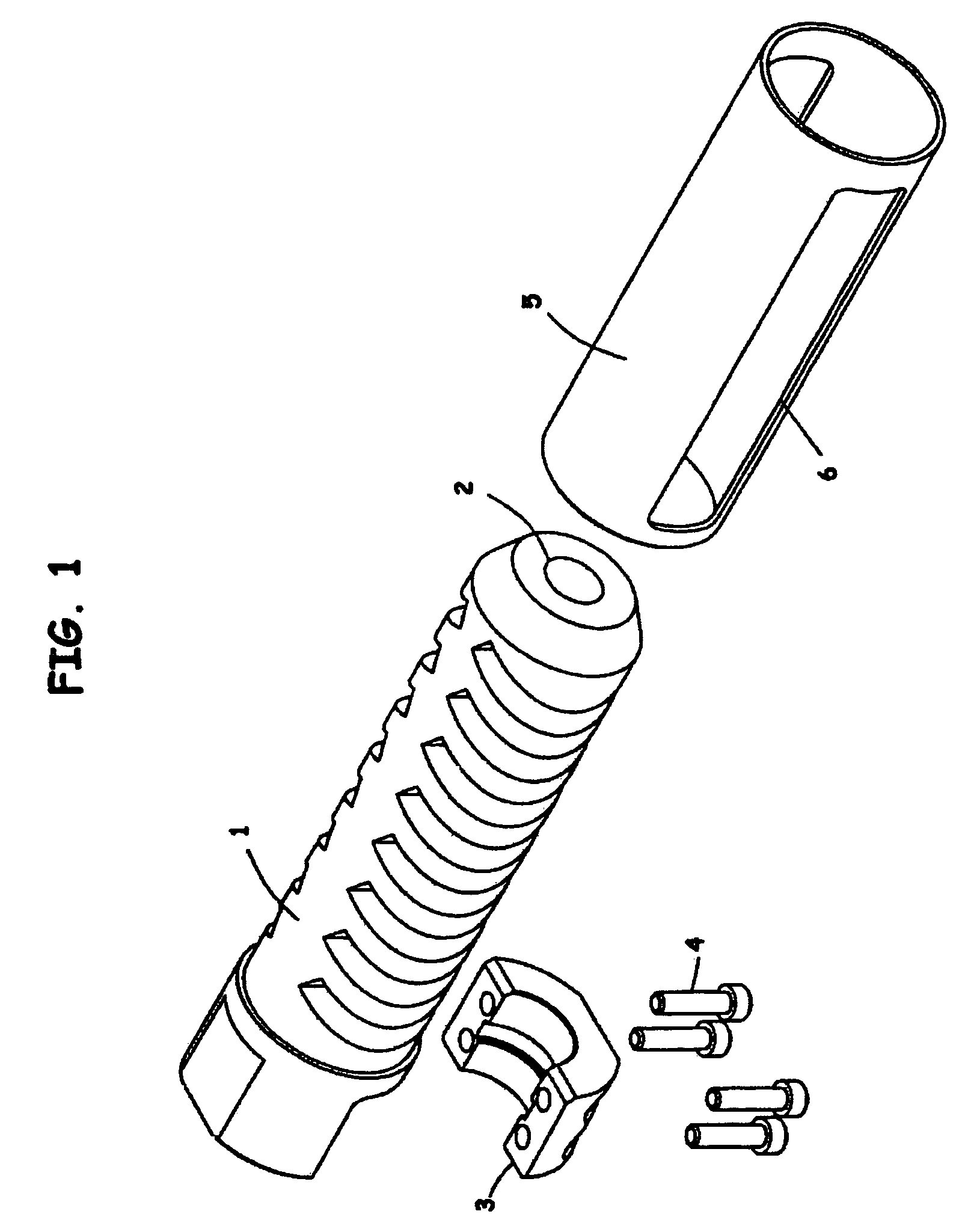
[0041]The recoil brake of the subject invention may be rigidly attached to a barrel muzzle either by a conventional threading, clamp or other suitable attachment. An embodiment of the subject recoil brake is shown in FIG. 1, where body 1 and exterior tube or tubular cover 5 comprise the brake and can be of various lengths and diameter to length aspect ratio. A bullet exit 2 is shown, and one type of barrel muzzle attachment comprising a clamp 3 and clamp fasteners 4. The exterior tube 6 may include at least one side port or exhaust slot 6. ...


PUM


Abstract

A recoil and muzzle blast dissipator may be attached to the barrel of a gun and may redirect propellant gasses. In one embodiment, a recoil and muzzle blast dissipater may include a body portion having an internal plenum and a plurality of vent slots, each vent slot having an aperture in communication with the internal plenum. Each successive vent slot may include an aperture that is larger in area than the aperture of the previous vent slot. An exterior tube may include a side port and may be arranged to overlay the body portion such that a portion of each vent slot is covered by the exterior tube, and a portion of each vent slot is in communication with the side port.

Description

CROSS-REFERENCE TO RELATED APPLICATIONS[0001]This application claims the benefit of U.S. Provisional Patent Application No. 60 / 461,121 filed Apr. 8, 2003, the entire contents of which are incorporated herein by reference.BACKGROUND OF THE INVENTION[0002]This invention relates to rifle muzzle brakes. More specifically, in at least one embodiment, the invention may comprise a felt-recoil and muzzle blast wave dissipator, which characteristics are complimentary and not mutually exclusive, especially employable on large caliber rifles.[0003]Muzzle brake designs are generally known. As the power of modern shoulder fired rifles has risen, so too has it become necessary to control the felt-recoil to make them more comfortable to shoot and to reduce movement of the gun and thereby enhance quick target reacquisition for follow-on shots at the target.[0004]Recoil is the rearward motion of the gun when the gun is fired. The physical process follows Newton's Law: for every action, there is an e...

Claims


Application Information

Patent Timeline
IPC IPC(8): F41A21/00F41A21/38
CPCF41A21/38
Inventor BENDER, TERRENCE D.
Owner BENDER TERRENCE D
Learn More