Leg joint assist device for legged movable robot

a technology for moving robots and legs, which is applied in the direction of mechanical control devices, process and machine control, instruments, etc., can solve the problems of large size and weight of electric motors, excessive energy loss owing to joule heat or the like, and large driving force to be generated to joint actuators to resist forces

Inactive Publication Date: 2006-12-05
HONDA MOTOR CO LTD
View PDF13 Cites 18 Cited by
  • Summary
  • Abstract
  • Description
  • Claims
  • Application Information

AI Technical Summary

Benefits of technology

[0030]By allowing the engagement member, such as the piston, to move in the reciprocating manner by the rotary motion to linear motion transforming means as above, bending / stretching motion between the pair of link members (rotary motion of the rotating shaft of the specific joint) is appropriately transmitted to the spring means through the engagement member. Thus, as described earlier, the auxiliary driving force (the elastic force) of the spring means can be appropriately changed in accordance with the bending angle between the pair of link members. In this case, the rotary motion to linear motion transforming means can be configured by the use of a crankshaft, a cam or the like. Therefore, the configuration thereof can be simple.

Problems solved by technology

Consequently, driving forces to be generated to the joint actuators to resist the forces are likely to become relatively large.
With any of these operations, however, it is required to energize the electric motor and a power source such as a battery with a high current.
Thus, an energy loss owing to Joule heat or the like is likely to be excessively large.
Further, since the electric motor with a large capacity is required, the size and weight of the electric motor become large.
However, in this biped mobile robot, the elastic force of the spring increases in the bending direction of the leg as the bending degree of the leg at the knee joint becomes increasingly large.
Consequently, the driving force of the joint actuator cannot be kept relatively small over the entire period of the movement of the biped mobile robot.
Therefore, the driving force generated to the joint actuator of the knee joint may end up being large.
As a result, it is difficult to improve utilization efficiency of the total energy of the robot.
Therefore, when the leg is fully bent during the free leg period and the like of each leg, the amount of elastic deformation of the spring becomes large.
Thus, it is required to use a spring which allows such a large amount of elastic deformation, resulting in a large configuration of the spring.

Method used


Image

  • Leg joint assist device for legged movable robot
  • Leg joint assist device for legged movable robot
  • Leg joint assist device for legged movable robot

Examples


first embodiment

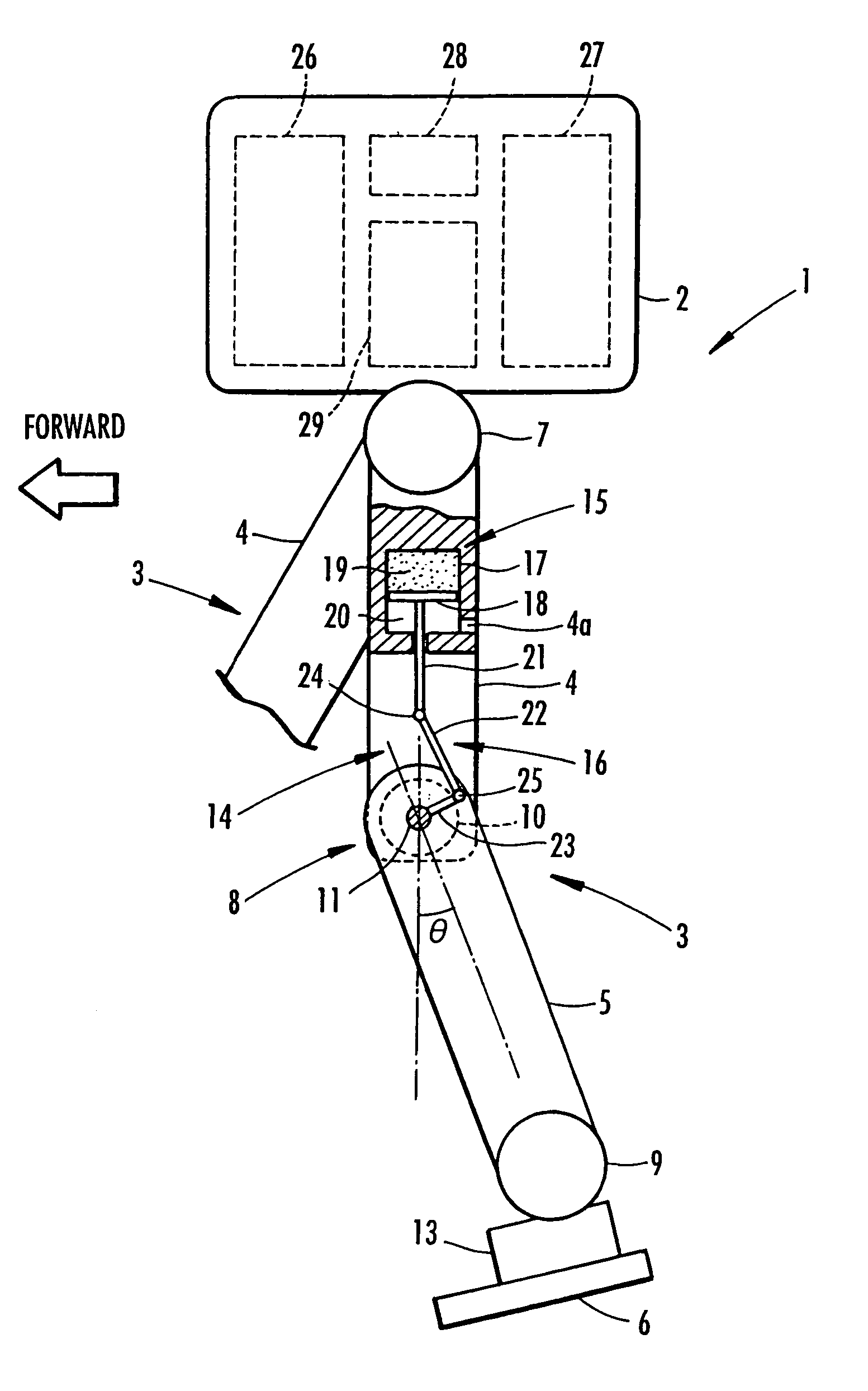
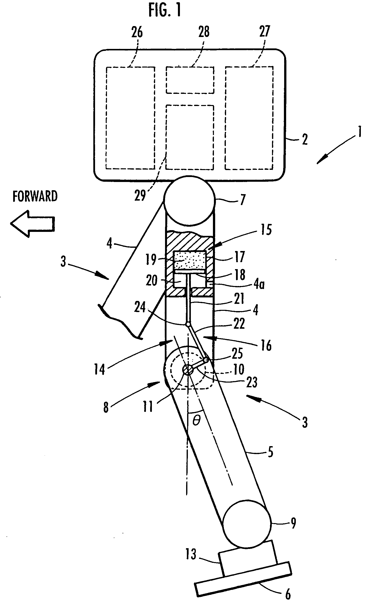
[0032]the present invention is described with reference to FIGS. 1 to 7. FIG. 1 is a schematic view depicting the configuration of a biped mobile robot serving as the legged mobile robot of this embodiment. As illustrated, the robot 1 is provided with two legs 3 and 3 extending downward from a body 2. Note that these legs 3 and 3 as well as later-described assist devices included therein have the same structure and thus one of the legs 3 (the forward-right leg 3 of the robot 1 in the figure) is shown only partially.

[0033]Similar to a leg of a human, each leg 3 is configured by sequentially connecting a thigh portion 4, a crus portion 5, and a foot portion 6 through a hip joint 7, a knee joint 8, and an ankle joint 9, respectively, from the body 2. To be more specific, the thigh portion 4 of each leg 3 extends from the body 2 through the hip joint 7, the crus portion 5 is connected to the thigh portion 4 through the knee joint 8, and the foot portion 6 is connected to the crus portio...

third embodiment

[0089]In this case, as shown by a solid line in FIG. 11, the cam surface of the cam 38′ is formed so that the auxiliary knee rotation force of the spring means 36 becomes the largest (maximum) in the stretching direction of the leg 3 at a predetermined angle θy1 which is smaller than the piston top dead center angle θx1 at which the auxiliary knee rotation force of the spring means 36 becomes “0”, and slightly larger than the foregoing supporting leg period maximum knee bending angle θa. In other words, the cam surface of the cam 38′ is formed as follows: when the knee bending angle θ is smaller than the aforementioned predetermined angle θy1 (hereinafter, referred to as a maximum auxiliary force angle θy1), the auxiliary knee rotation force of the spring means 36 increases in the stretching direction of the leg 3 as the knee bending angle θ increases; and, when the knee bending angle θ is larger than the maximum auxiliary force angle θy1, the auxiliary knee rotation force in the st...

fourth embodiment

[0091]Note that, the following is also feasible regarding the above-described In a case where the piston top dead center angle θx1 is set larger (for example, larger than the free leg period maximum knee bending angle θb), the auxiliary knee rotation force of the spring means 36 does not change in the bending direction of the leg 3 as long as a knee bending angle θ is smaller than the free leg period maximum knee bending angle θb, even though the knee bending angle θ exceeds the maximum auxiliary force angle θy1.

[0092]Furthermore, in the case where the piston top dead center angle θx1 is set even larger, the cam surface of the cam 38′ is formed so that the radius at the point where the cam surface of the cam 38′ contacts the aforementioned roller 40 changes less acutely than the case of the foregoing fourth embodiment, relative to the knee bending angle θ. Thus, the auxiliary knee rotation force of the spring means 36 can be kept almost invariant (the auxiliary knee rotation force ...


PUM


Abstract

An assist device is provided with a spring device that generates an auxiliary driving force, by an elastic energy, acting on a joint of a leg. The spring device includes a gas spring having a cylinder and a piston. Bending/stretching motion between link members and at the joint is transmitted to the spring device through a motion transmission device that includes a link arm. The spring device is provided so that the auxiliary driving force increases as a knee bending angle θ increases until the knee bending angle θ reaches a predetermined angle, and so that, once the knee bending angle θ exceeds the predetermined angle, the auxiliary driving force becomes smaller than or equal to the driving force obtaining at the predetermined angle, effectively reducing a burden on an actuator of the legged mobile robot joint.

Description

TECHNICAL FIELD[0001]The present invention relates to a leg joint assist device which generates an auxiliary driving force to a joint of a leg of a legged mobile robot such as a biped mobile robot, to assist a joint actuator driving the joint.BACKGROUND ART[0002]In a legged mobile robot having a plurality of legs, each being configured by sequentially connecting a plurality of link members from a body through a plurality of joints. For example, in a biped mobile robot having two legs like a human, each leg is configured by sequentially connecting the link members, which correspond to a thigh portion, a crus portion, and a foot portion, through a hip joint, a knee joint, and an ankle joint, respectively, from the body of the robot. In addition, in the legged mobile robot of this kind, each leg's motion for moving the robot is produced by applying driving forces to the joints of each leg by using joint actuators such as electric motors.[0003]Incidentally, in this kind of mobile robot,...

Claims


Application Information

Patent Timeline
Patent Type & Authority Patents(United States)
IPC IPC(8): B62D51/06B25J5/00B25J19/00B62D57/032
CPCB25J19/0012B62D57/032Y10T74/20305
Inventor TAKENAKA, TORUGOMI, HIROSHIHAMAYA, KAZUSHITAKEMURA, YOSHINARI
Owner HONDA MOTOR CO LTD
Why Eureka
Try Eureka