
Propeller

a propeller and blade technology, applied in the field of propellers, can solve the problems of propellers being limited to a smaller diameter than desired, heavy propellers, and affecting the performance of propellers, so as to reduce the stress, improve performance, and increase the effect of siz

Inactive Publication Date: 2006-12-05
MEDTRONIC INC
View PDF9 Cites 37 Cited by
  • Summary
  • Abstract
  • Description
  • Claims
  • Application Information

AI Technical Summary

Benefits of technology

[0009]It is a further object of the present invention to provide a lighter propeller that reduces the stresses imparted on the blade attachment components, main shaft and main shaft bearings that must support the weight of the propeller.
[0010]It is a further object of the present invention to provide a propeller that can be increased in size for better performance without exerting excessive forces on the blade attachment components, main shaft and main shaft bearings. Alternatively, the size and mechanical properties of the blade attachment components, main shaft and main shaft bearings can be reduced since they are exposed to lower forces due to weight of the propeller, thereby reducing the weight of the propulsion system as a whole.
[0011]It is a further object of the present invention to reduce compromises in the shape and configuration of the propeller due to the weight of the propeller.
[0012]It is a further object of the present invention to provide a propeller that can be tuned with respect to modal / vibrational characteristics, as compared to solid propellers, by the addition of fill materials to the generally hollow interior of the blade It is a further object of the present invention to provide a propeller that can be tuned by varying lattice support spar density, alignment and / or configuration, either uniformly or nonuniformly within the propeller.

Problems solved by technology

The combination of size and material makes the propeller quite heavy and places great mechanical stresses on the blade attachment components, main shaft and main shaft bearings that must support the weight.
The propeller can even be limited to a smaller diameter than desired for an application because the weight of a larger propeller imparts excessive stresses on such components.
Large propellers solid cast propellers and propeller blades can also have material cross-section dimensions that are so large that the solidification of the material results in non-optimal through-section microstructure and reduced mechanical strength properties, such as tensile strength, yield strength, elongation and fatigue life.
This, however, can result in compromised cavitation performance and reduced mechanical strength properties of the propeller.
Although such propellers can be balanced by the addition or removal of material to one or more of the blades, there are limitations to the manner such balancing can be performed while preserving the performance and structural integrity of the propeller.

Method used


Image

  • Propeller
  • Propeller
  • Propeller

Examples


Embodiment Construction

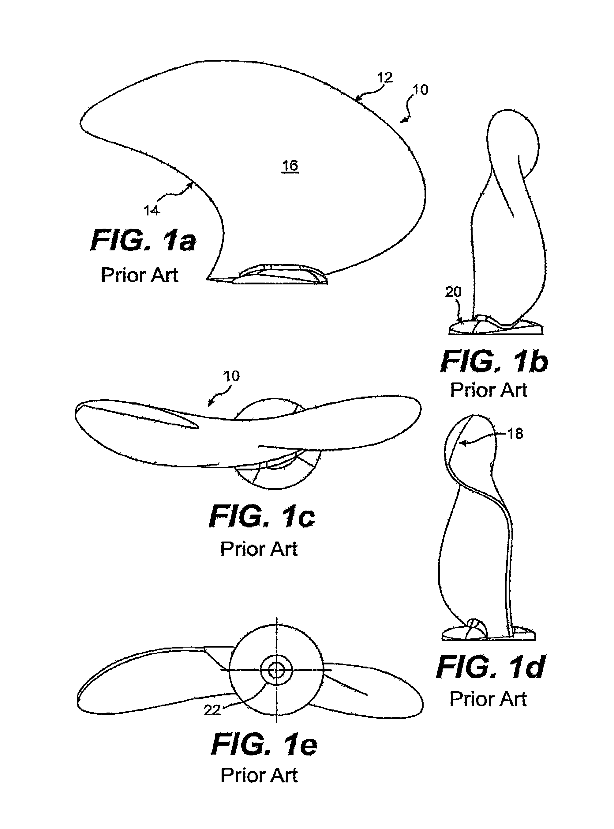
[0021]FIGS. 1a–e (Prior Art) show five views of a known propeller blade 10 constructed for attachment to a central propeller hub in a known manner. The blade 10 includes a leading edge 12, a trailing edge 14, a blade surface 16, a tip 18, a flange 20 for mounting to a central propeller hub and a balance pocket 22 where material can be added or removed to alter the weight of the blade 10 and thus, the balance of the propeller. For purposes of this description, the term propeller is used whether it is in a driving mode, as with a propeller for a ship or airplane, or a driven mode, as with a turbine or windmill.

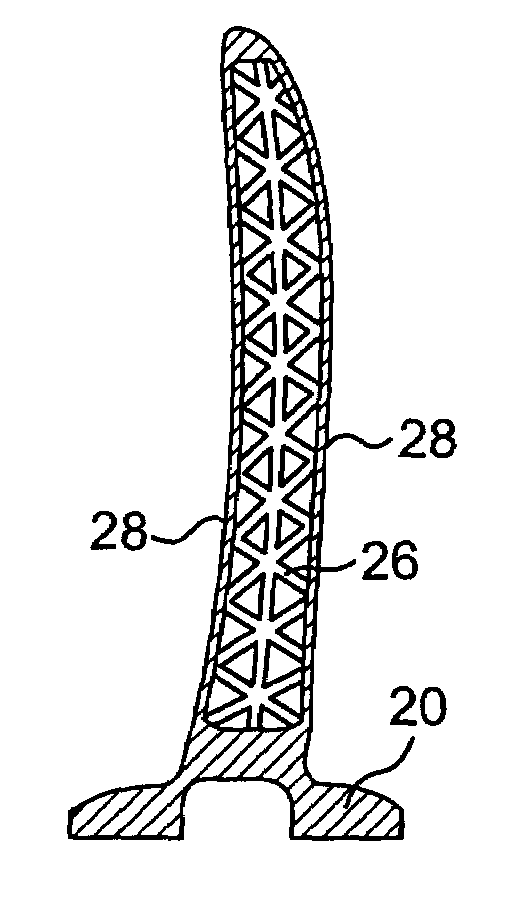
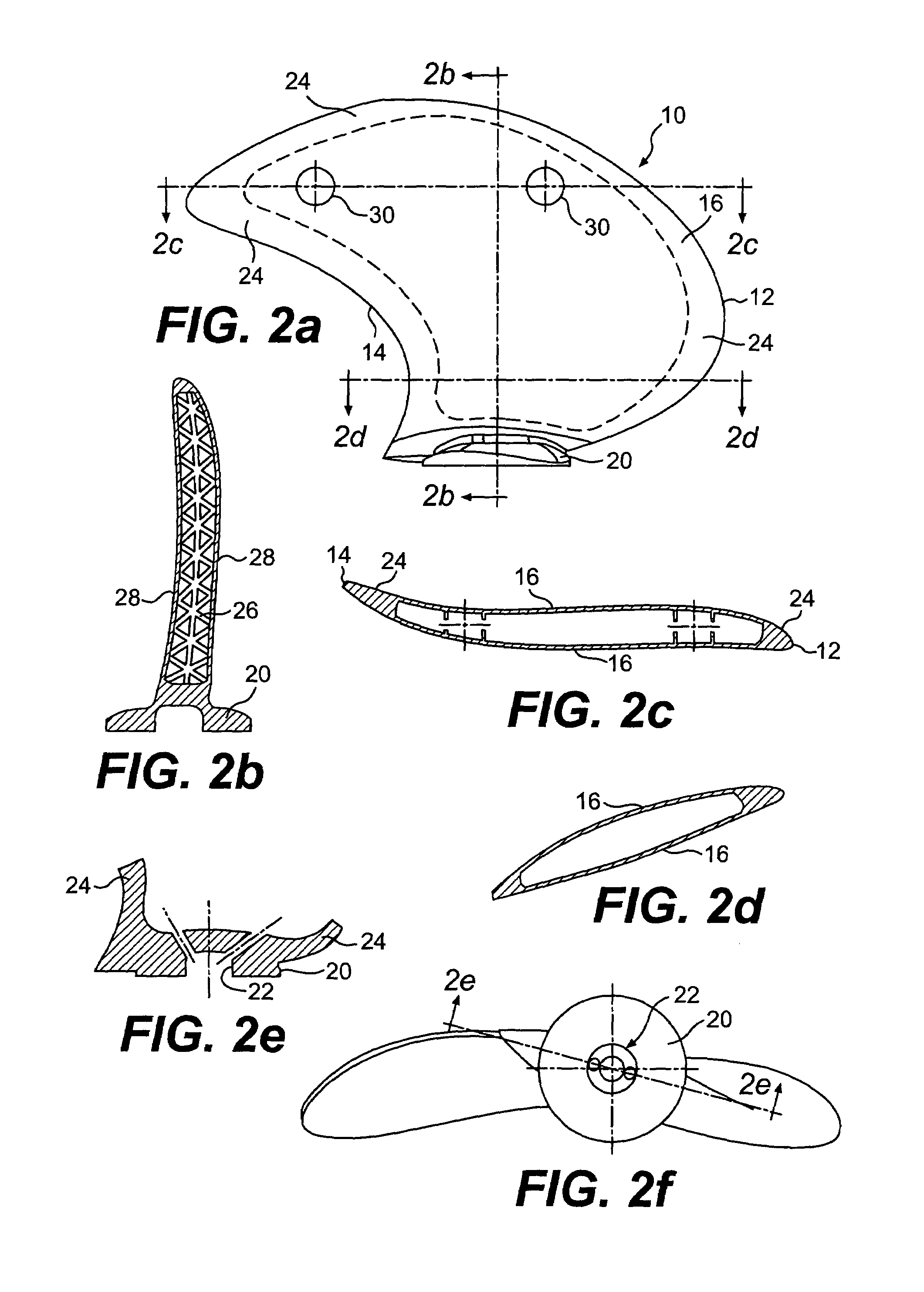
[0022]FIGS. 2a–f show six views of a propeller blade 10 according to a first embodiment of the present invention. The blade 10 can have the same general configuration as the blade shown in FIG. 1 or can have a different configuration, as desired. The blade 10 includes a periphery 24 that is cast in a generally solid manner, integral with the flange 20. Within this periphery, the...


PUM


Abstract

A propeller or propeller blade is manufactured using lattice block material to provide a structure which is generally hollow but for a three-dimensional lattice of support spars. The propeller or propeller blade, being predominately hollow, is substantially lighter than a solid cast propeller or propeller blade while retaining the desired strength due to the three-dimensional lattice of support spars.

Description

[0001]This application claims priority to U.S. patent application Ser. No. 60 / 375,713 filed Apr. 29, 2002, the entirety of which is incorporated by reference herein.BACKGROUND OF THE INVENTION[0002]The present invention relates to a propeller and method for manufacturing same, and more particularly, to a propeller manufactured using a lattice block material.[0003]Propellers for ships are quite large, often spanning over 10 feet in diameter and are typically made of a bronze alloy. The propellers can be manufactured as a single casting or can be designed to have a plurality of blades cast separately that are then attached to a separate central hub, with the respective components being generally solid castings. The combination of size and material makes the propeller quite heavy and places great mechanical stresses on the blade attachment components, main shaft and main shaft bearings that must support the weight. The propeller can even be limited to a smaller diameter than desired fo...

Claims


Application Information

Patent Timeline
Patent Type & Authority Patents(United States)
IPC IPC(8): B64C11/24F01D5/14B63H1/26
CPCB63H1/26
Inventor LANNI, FRANCESCOECKHART, JOHN A.
Owner MEDTRONIC INC
Learn More