

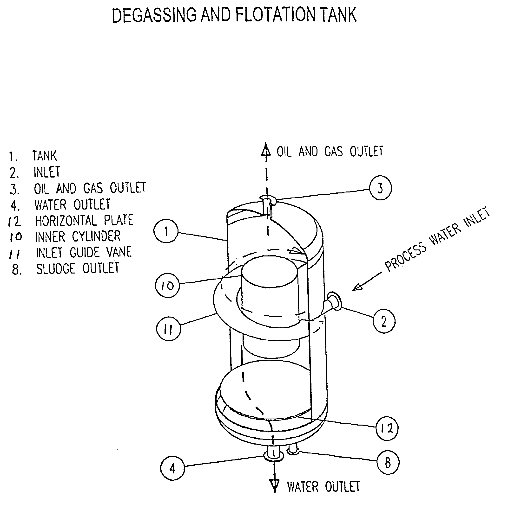
Combined degassing and flotation tank
a flotation tank and flotation tank technology, which is applied in the direction of sedimentation settling tanks, settling tank feed/discharge, borehole/well accessories, etc., can solve the problem of very modest space requirement in relation to the amount of treated water, and achieve the effect of high efficiency, very high throughput of the tank and modest space requiremen
- Summary
- Abstract
- Description
- Claims
- Application Information
AI Technical Summary
Benefits of technology
Problems solved by technology
Method used
Image

Examples
example 1
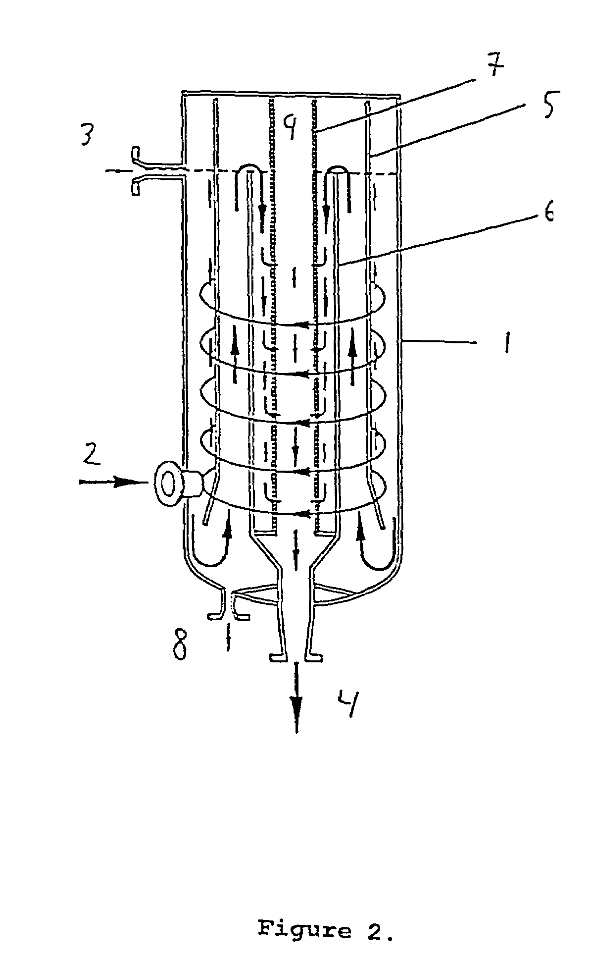
[0069]A combined degassing and flotation tank corresponding to FIG. 2, having a diameter of 500 mm and a height of 1200 mm and an efficient flotation volume of 125 litre, was tested on water phase effluent from a second step oil separator from a commercial oil production platform. The sample water contained varying amounts of oil and gas in the range equivalent to approximately 50–200 mg hydrocarbon per litre. The intake varied between 1.8 and 9.5 m3 / h.
[0070]The output water contained approximately 20 mg hydrocarbon per litre or less, during most of the experiments less than 20 mg / l. The efficiency of cleaning calculated as percentage hydrocarbon removed was during most of the experiment between 80 and 90%.
[0071]The actual data is shown in FIG. 4, which is a graph showing the concentrations of hydrocarbons in the inlet and the effluent stream of the combined degassing and flotation tank measured at regular intervals during the experiment.
example 2
A combined degassing and flotation tank was designed essentially as depicted in FIG. 3 having the following dimensions:
[0072]
Height2530 mmDiameter of tank1130 mmDiameter of inner cylinderappx. 500 mm
And the inner cylinder extending approximately ⅔ down into the tank.
[0073]This combined degassing and flotation tank was run in a full scale with an inlet of 150 m3 / h.
[0074]The plant was operated continuous with out breaks in more that 6 months with an inlet of water contaminated with approximately 200–600 ppm hydrocarbonaceous oil and gas and an outlet containing 5–10 ppm.
[0075]This study confirms the high throughput with high cleansing efficiency essentially without need for intermittently breaks for maintenance.
PUM
| Property | Measurement | Unit |
|---|---|---|
| pressure | aaaaa | aaaaa |
| pressure | aaaaa | aaaaa |
| residence time | aaaaa | aaaaa |
Abstract
Description
Claims
Application Information