Microfabricated elastomeric valve and pump systems

Inactive Publication Date: 2006-12-05
CALIFORNIA INST OF TECH
View PDF88 Cites 268 Cited by
  • Summary
  • Abstract
  • Description
  • Claims
  • Application Information

AI Technical Summary

Benefits of technology

[0018]A further advantage of the present monolithic elastomeric valve and pump structures are that they can be actuated at very high speeds. For example, the present inventors have achieved a response time for a valve with aqueous solution therein on the order of one millisecond, such that the valve opens and closes at speeds approaching or exceeding 100 Hz. In particular, a non-exclusive list of ranges of cycling speeds for the opening and closing of the valve structure include between about 0.001 and 10000 ms, between about 0.01 and 1000 ms, between about 0.1 and 100 ms, and be

Problems solved by technology

Unfortunately, each of these approaches suffers from its own limitations.
A limitation of the first approach of silicon-based micro-machining is that the stiffness of the semiconductor materials used necessitates high actuation forces, which in turn result in large and complex designs.
In fact, both bulk and surface micro-machi

Method used


Image

  • Microfabricated elastomeric valve and pump systems
  • Microfabricated elastomeric valve and pump systems
  • Microfabricated elastomeric valve and pump systems

Examples


Example

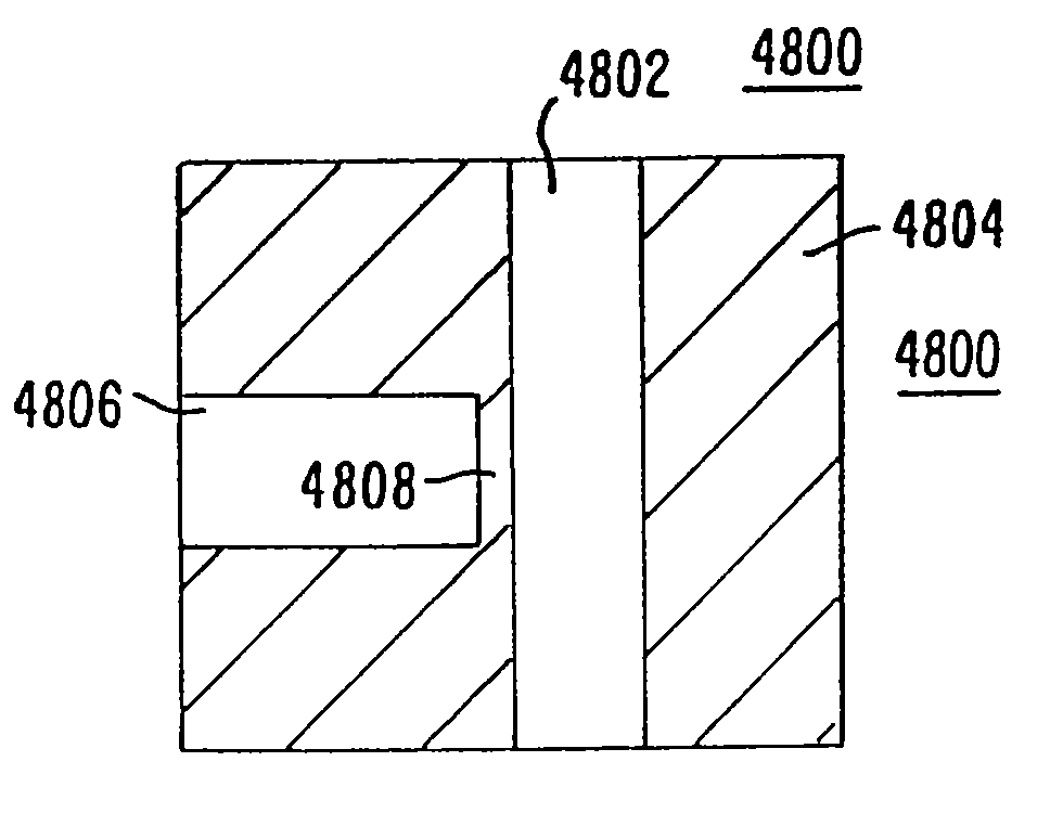
[0094]The present invention comprises a variety of microfabricated elastomeric structures which may be used as pumps or valves. Methods of fabricating the preferred elastomeric structures are also set forth.

[0095]Methods of Fabricating the Present Invention:

[0096]Two exemplary methods of fabricating the present invention are provided herein. It is to be understood that the present invention is not limited to fabrication by one or the other of these methods. Rather, other suitable methods of fabricating the present microstructures, including modifying the present methods, are also contemplated.

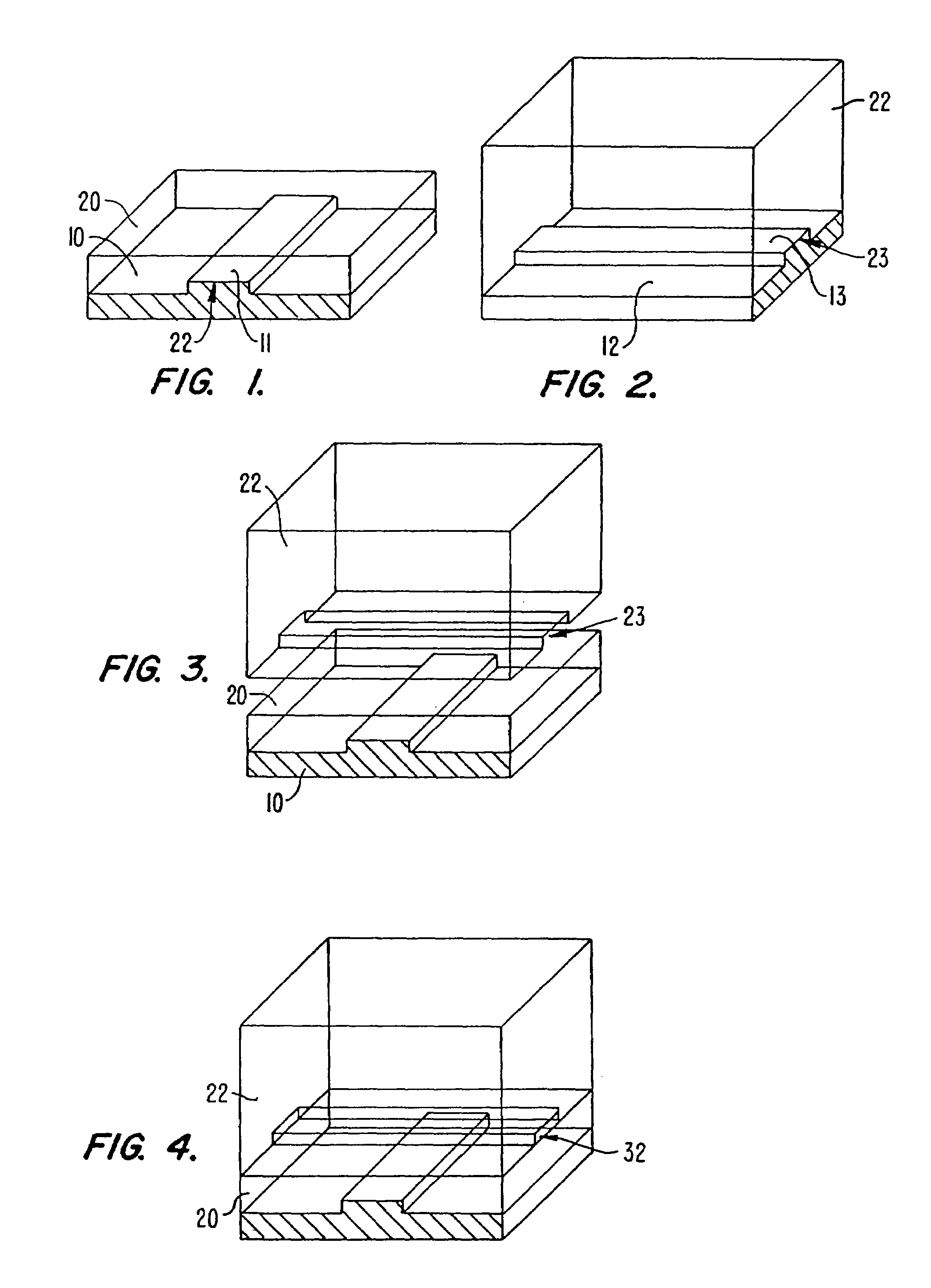
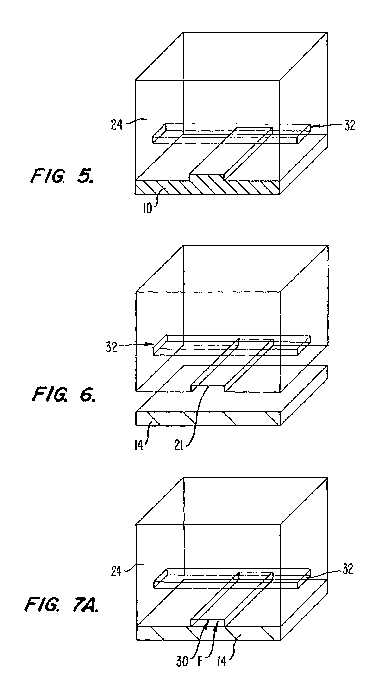
[0097]FIGS. 1 to 7B illustrate sequential steps of a first preferred method of fabricating the present microstructure, (which may be used as a pump or valve). FIGS. 8 to 18 illustrate sequential steps of a second preferred method of fabricating the present microstructure, (which also may be used as a pump or valve).

[0098]As will be explained, the preferred method of FIGS. 1 to 7B involves using...


PUM

PropertyMeasurementUnit
Widthaaaaaaaaaa
Flow rateaaaaaaaaaa
Structureaaaaaaaaaa

Abstract

A method of fabricating an elastomeric structure, comprising: forming a first elastomeric layer on top of a first micromachined mold, the first micromachined mold having a first raised protrusion which forms a first recess extending along a bottom surface of the first elastomeric layer; forming a second elastomeric layer on top of a second micromachined mold, the second micromachined mold having a second raised protrusion which forms a second recess extending along a bottom surface of the second elastomeric layer; bonding the bottom surface of the second elastomeric layer onto a top surface of the first elastomeric layer such that a control channel forms in the second recess between the first and second elastomeric layers; and positioning the first elastomeric layer on top of a planar substrate such that a flow channel forms in the first recess between the first elastomeric layer and the planar substrate.

Description

CROSS-REFERENCE TO RELATED APPLICATIONS[0001]This nonprovisional patent application is a continuation-in-part of parent nonprovisional patent application Ser. No. 09 / 605,520, filed Jun. 27, 2000. The parent application claims the benefit of the following previously filed provisional patent applications: U.S. provisional patent application No. 60 / 141,503 filed Jun. 28, 1999, U.S. provisional patent application No. 60 / 147,199 filed Aug. 3, 1999, and U.S. provisional patent application No. 60 / 186,856 filed Mar. 3, 2000. The text of these prior provisional patent applications is hereby incorporated by reference.STATEMENT AS TO RIGHTS TO INVENTIONS MADE UNDER FEDERALLY SPONSORED RESEARCH AND DEVELOPMENT[0002]Work described herein has been supported, in part, by National Institute of Health grant HG-01642-02. The United States Government may therefore have certain rights in the invention.TECHNICAL FIELD[0003]The present invention relates to microfabricated structures and methods for produ...

Claims


Application Information

Patent Timeline
IPC IPC(8): B32B3/00F16C1/06F16K1/00F16K31/145F16K7/00B01L3/00B01L7/00B01L9/00B67D99/00B81B1/00B81B3/00B81C1/00C12Q1/68F04B43/04F15C5/00
CPCB01L3/502707B01L3/50273B01L3/502738B01L9/527B81C1/00119C12Q1/6874F04B43/043F15C5/00F16K99/0001F16K99/0015F16K99/0046F16K99/0051F16K99/0059B01J2219/00355Y10T428/24744B01J2219/00396B01J2219/00398B01J2219/00439B01J2219/005B01J2219/00527B01J2219/00605B01J2219/00612B01J2219/00659B01J2219/00707B01J2219/00722B01J2219/00725B01L7/54B01L2200/025B01L2200/027B01L2200/0605B01L2200/10B01L2300/0681B01L2300/0861B01L2300/0887B01L2300/123B01L2300/14B01L2300/18B01L2400/046B01L2400/0481B01L2400/0655B01L2400/0688B32B2037/1081B81B2201/036B81B2201/054B81C2201/019F16K2099/0074F16K2099/0076F16K2099/0078F16K2099/008F16K2099/0094B01J2219/00378Y10T428/24612Y10T428/24479Y10T156/1064Y10T156/10Y10T156/1002Y10T428/2457C12Q2535/125Y10T137/0491Y10T137/87812Y10T137/87804Y10T137/2224Y10T137/87716Y10T137/87893F04B43/14B32B3/00B81B3/0032B81B3/0051
Inventor UNGER, MARC A.CHOU, HOU-PUTHORSEN, TODD A.SCHERER, AXELQUAKE, STEPHEN R.
Owner CALIFORNIA INST OF TECH
Why Eureka
Try Eureka