
Method and apparatus for thermally processing microelectronic workpieces

a technology for microelectronic workpieces and equipment, applied in lighting and heating equipment, furniture, transportation and packaging, etc., can solve the problems of device failure, device failure, and affecting the polish rate of chemical mechanical processing as well as the ultimate uniformity of the surface of the polished copper structure, so as to improve equipment reliability, reduce the throughput time of the thermal process, and increase manufacturing efficiencies

Inactive Publication Date: 2006-12-05
APPLIED MATERIALS INC
View PDF8 Cites 11 Cited by
  • Summary
  • Abstract
  • Description
  • Claims
  • Application Information

AI Technical Summary

Benefits of technology

The present invention provides a method and apparatus for thermally processing microelectronic workpieces. The apparatus includes a rotatable carousel assembly for holding multiple workpieces and a process fluid distribution system for delivering process fluid to each workpiece. The method involves sequentially rotating each workpiece from a loading station, a heating station, and a cooling station while maintaining the workpiece at a desired temperature. The continuous process allows for efficient and uniform transfer of thermal energy to the workpieces, resulting in increased throughput, more efficient energy expenditures, and improved equipment reliability.

Problems solved by technology

Wafer-to-wafer and within wafer grain size variability in the copper film can adversely affect the polish rate of the chemical mechanical processing as well as the ultimate uniformity of the surfaces of the polished copper structures.
Such devices may fail if the copper metallization exhibits excessive electromigration that ultimately results in an open or short circuit condition in one or more of the metallization structures.
These conventional thermal processing units present a number of drawbacks.
First, the cost of batch equipment is higher due to the extra components to handle workpiece transport.
Further, batch thermal processing typically requires massive heating and cooling elements, which typically require relatively long periods of time in order to change from one temperature and come to equilibrium at a new temperature.
Moreover, a large amount of energy is required to heat and cool the massive elements.
Heating and cooling in a single process chamber takes relatively long periods of time, reducing the throughput of the manufacturing process.
Finally, exposing heating and cooling elements to repetitive temperature cycling leads to process equipment fatigue and eventually failure.

Method used


Image

  • Method and apparatus for thermally processing microelectronic workpieces
  • Method and apparatus for thermally processing microelectronic workpieces
  • Method and apparatus for thermally processing microelectronic workpieces

Examples


Embodiment Construction

[0046]For purposes of the present application, a microelectronic workpiece is defined to include a workpiece formed from a substrate upon which microelectronic circuits or components, data storage elements or layers, and / or micromechanical elements are formed. Although the present invention is applicable to this wide range of products, the invention will be particularly described in connection with its use in the production of interconnect structures formed during the production of integrated circuits on a semiconductor wafer. Still further, although the invention is applicable for use in connection with a wide range of metal and metal alloys as well as in connection with a wide range of elevated temperature processes, the invention will be particularly described in connection with annealing of electroplated copper and copper alloys.

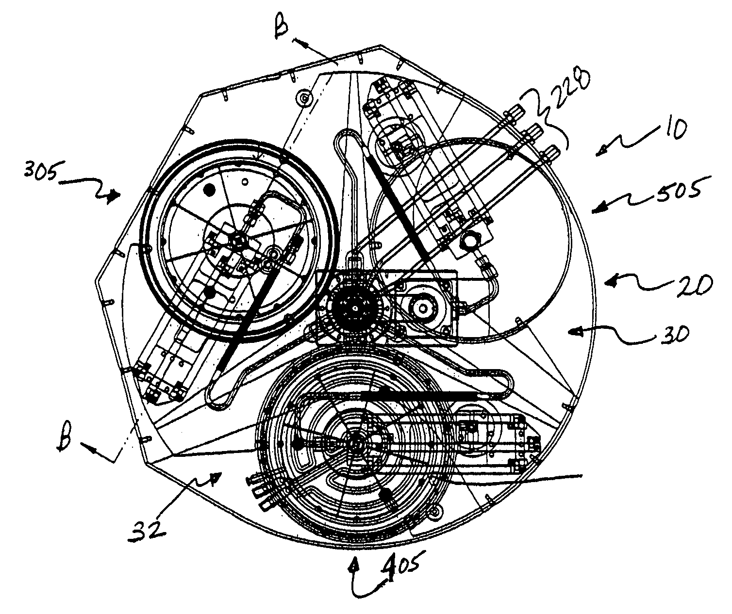
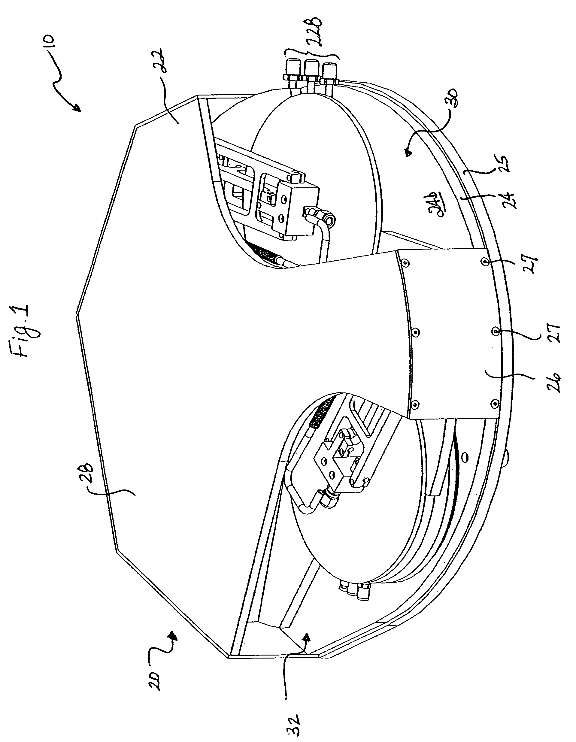
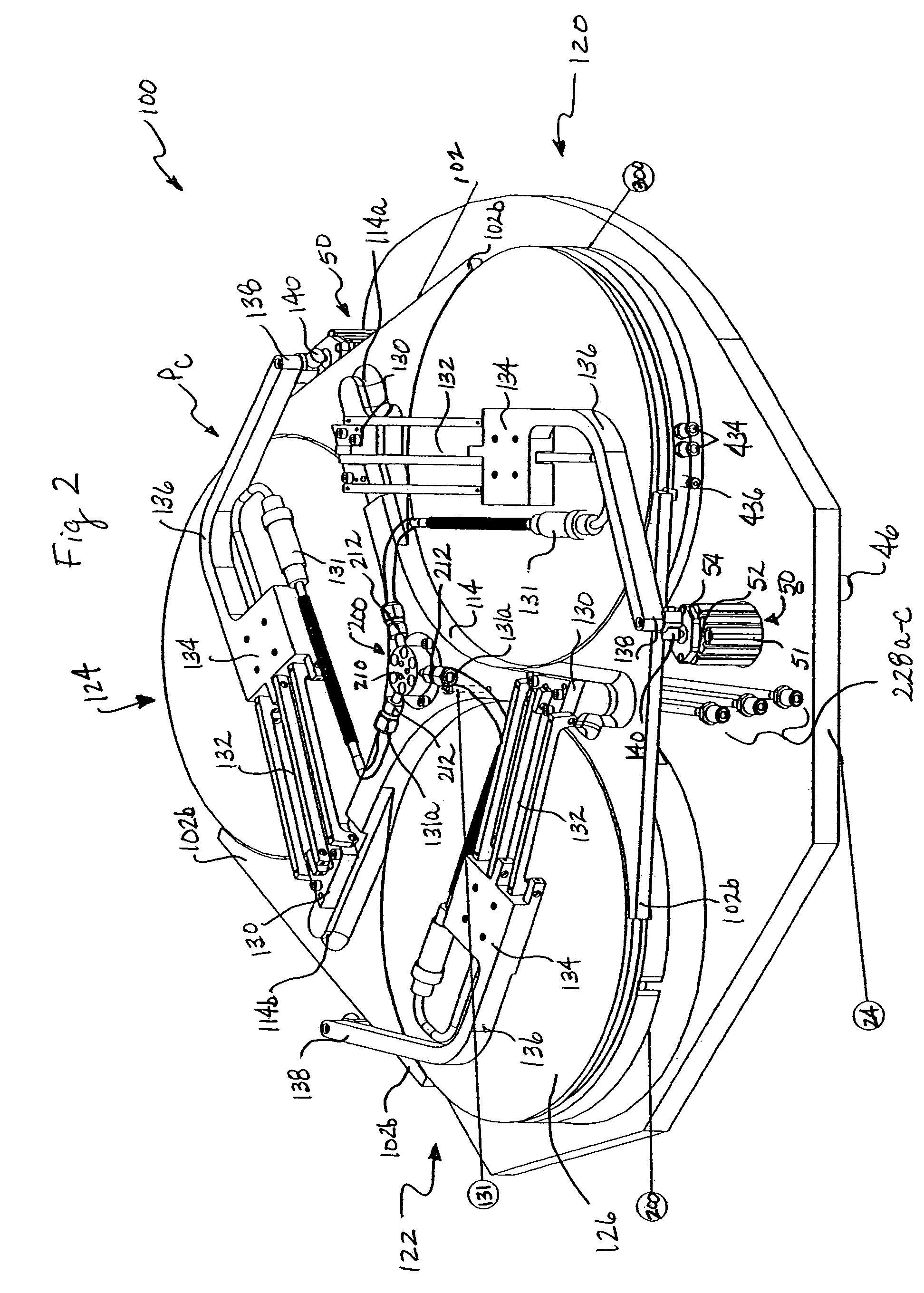
[0047]The present invention generally relates to an apparatus 10 and method for thermally processing microelectronic workpieces W. Referring to FIGS. 1 ...


PUM


Abstract

An apparatus for thermally processing a microelectronic workpiece is provided. The apparatus comprises a rotatable carousel assembly configured to support at least one workpiece. A driver is coupled to the carousel assembly and rotates the carousel assembly, moving the workpiece between a loading station, a heating station and a cooling station. The loading, heating and cooling stations are radially positioned and approximately equally spaced about a center axis of the carousel assembly. The heating station includes a heating element and an actuator for moving the heating element into thermal engagement with the workpiece in the heating station. The cooling station includes a cooling element and an actuator for moving the cooling element into thermal engagement with the workpiece in the cooling station. A process fluid distribution manifold for delivering process fluid to the workpieces at each station extends through a central opening in the carousel assembly. A non-oxidizing gas is delivered through the manifold to create an oxygen free environment during the thermal process.

Description

CROSS-REFERENCE TO RELATED APPLICATIONS[0001]Not Applicable.TECHNICAL FIELD[0002]The present invention is generally directed to a method and apparatus for thermally processing one or more microelectronic workpieces. More specifically, the apparatus includes a carousel assembly that rotates the workpiece between a loading station, a heating station and a cooling station positioned radially outwardly from a central axis of the carousel assembly.BACKGROUND OF THE INVENTION[0003]In the production of semiconductor integrated circuits and other microelectronic articles from microelectronic workpieces, such as semiconductor wafers, it is often necessary to provide multiple metal layers on a substrate to serve as interconnect metallization that electrically connects the various devices on the integrated circuit to one another. Traditionally, aluminum has been used for such interconnects, however, it is now recognized that copper metallization may be preferable. Copper interconnects can help...

Claims


Application Information

Patent Timeline
Patent Type & Authority Patents(United States)
IPC IPC(8): H01L21/302
CPCH01L21/67109H01L21/67748Y10S438/907Y10S438/908
Inventor WIRTH, PAUL ZACHARYDAVIS, JEFFRY ALAN
Owner APPLIED MATERIALS INC
Learn More