Methanol synthesis

a technology of methanol and synthesis, which is applied in the field of methanol synthesis, can solve the problems of reducing the amount of heat recovered prior to the tube-cooled bed, not making the best use of the tube-cooled bed, and pre-heating the bed, so as to achieve efficient heat recovery and better control of the temperature

Inactive Publication Date: 2006-12-05
JOHNSON MATTHEY PLC
View PDF10 Cites 26 Cited by
  • Summary
  • Abstract
  • Description
  • Claims
  • Application Information

AI Technical Summary

Benefits of technology

[0006]We have devised an alternative arrangement that provides better control of the temperature of the synthesis gas and more efficient heat recovery than the processes described previously.
[0009]Thus in distinction to the arrangement described in the aforesaid U.S. Pat. No. 5,827,901, the synthesis gas used as coolant flows co-currently instead of counter-currently through the heat exchange reactor. Also the reactor cooled by boiling water is replaced by one or more uncooled beds of catalyst in which the synthesis proceeds adiabatically and the heat is recovered as a separate step after at least the first uncooled catalyst bed, and preferably after passage through each uncooled bed except, possibly, the last uncooled bed preceding the bed having the cooling tubes disposed therein. For convenience an uncooled bed will be termed an adiabatic bed and the bed having the coolant tubes extending therethrough will be termed the tube-cooled bed. The partially reacted synthesis gas is preferably not cooled after the last adiabatic bed and before entry into the tube-cooled bed. Thus in a preferred arrangement, the last adiabatic bed before the tube-cooled bed is in effect a “pre-heating” bed sized such that it acts, by virtue of the adiabatic synthesis reaction occurring therein, to heat the synthesis gas from the outlet temperature of the heat recovery step to the desired inlet temperature for the tube-cooled bed. While it is possible to dispose this bed in a separate vessel, in many cases this last adiabatic bed may simply be formed as a layer of catalyst on top of the body of catalyst in the tube-cooled bed. While such a “preheating” bed may be omitted, such omission is less advantageous as the initial part of the tube-cooled bed would have to be employed partly as a region for heating the synthesis gas to the desired maximum synthesis temperature. This would not make the best use of tube-cooled bed. An alternative, or additional, disadvantage of omission of the “pre-heating” bed would be a decrease in the amount of heat recovered prior to the tube-cooled bed. Thus if there was no “pre-heating” bed, and it was desired to make the best use of the tube-cooled bed, then it is necessary that the temperature of the partially reacted gas leaving the heat recovery stage preceding the tube-cooled bed is greater so that the temperature of the partially reacted gas entering the tube-cooled bed is at, or close, to the desired maximum synthesis temperature. Increasing the temperature of the partially reacted gas leaving the heat recovery stage, decreases the temperature differential between the inlet and outlet temperatures of the partially reacted gas undergoing cooling in that heat recovery stage. Decreasing the temperature differential decreases the amount of heat recovered.
[0010]Co-current, rather than counter-current, flow of the coolant is advantageous as it enables the tube-cooled bed to operate with a lower peak catalyst temperature (thereby increasing catalyst life and decreasing the amount of by-product formation) and enables the temperature profile in the heat exchange reactor to match more closely the profile corresponding to the maximum rate of methanol synthesis. However one disadvantage of co-current coolant flow is that the temperature of the coolant and product reacted gas leaving the heat exchange reactor is generally too low to recover high grade heat. By subjecting the heated coolant to one or more stages of adiabatic methanol synthesis, followed by heat recovery, higher grade heat can be recovered. The use of adiabatic synthesis catalyst beds plus separate heat recovery is advantageous compared to a system employing a heat exchange reactor using water boiling under pressure as a coolant as it is more flexible. A system using water boiling under pressure is essentially isothermal and the temperature is dictated by the pressure. If the resultant steam is to be used as process steam used to produce the synthesis gas (for example by steam reforming of a hydrocarbon feedstock), the pressure of the reforming operation is thus dictated by the temperature at which the boiling water cooled reactor is to be operated. In contrast, separation of the heat recovery step from the methanol synthesis, by using an adiabatic bed and separate heat recovery, enables higher grade heat to be recovered.
[0012]The methanol synthesis may be performed at pressures in the range 40–150, and more conveniently in the range 45–120, bar abs. The temperature of the synthesis catalyst is suitably in the range 160–300° C.; preferably the peak temperature is below 285° C. The synthesis gas preferably enters the catalyst beds at a temperature in the range 200–250° C. and leaves the beds at temperatures preferably in the range 220–260° C. Such temperatures provide for an acceptable methanol output rate (owing to favourable equilibrium) without producing the greater content of by-product impurities, and reduction in catalyst life, that would result from operation at higher temperatures.

Problems solved by technology

This would not make the best use of tube-cooled bed.
An alternative, or additional, disadvantage of omission of the “pre-heating” bed would be a decrease in the amount of heat recovered prior to the tube-cooled bed.

Method used


Image

  • Methanol synthesis
  • Methanol synthesis
  • Methanol synthesis

Examples


example 1

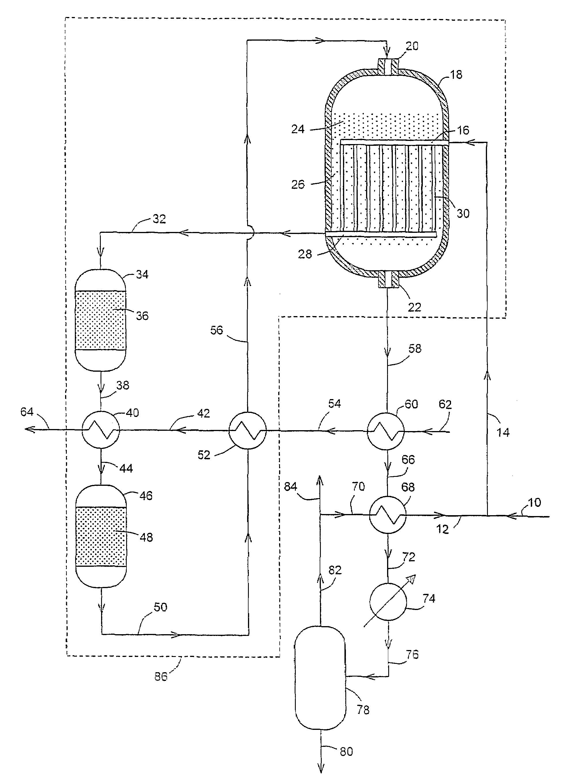
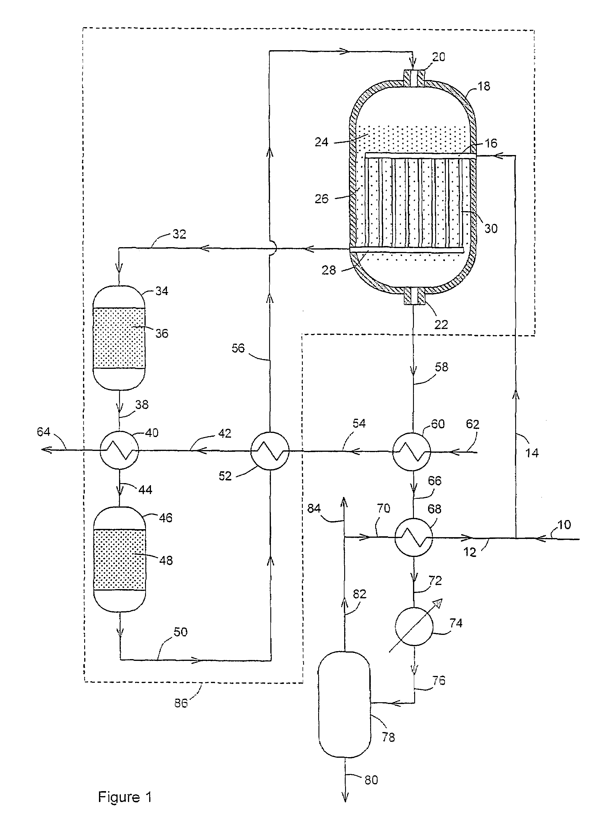
[0037]In this example the flowsheet is as shown in FIG. 1. The results are shown in Table 1. For convenience of calculation and comparison, the volume of catalyst in bed 26 below the coolant outlet header 28 is assumed to be negligible.

[0038]

TABLE 1Pres-sureTemp(barFlow rate (kmol / h)stream(° C.)abs.)H2COCO2H2OinertsCH3OH1013085.0933019838753847601217785.0319375007862346721921416585.041267248316616151481923223084.541267248316616151481923827584.03881720861109613514811414423583.53881720861109613514811415027583.03743314911045678514818015624082.53743314911045678514818015824081.53505154987884451482908804580.310119818212698824580.335041548859265127211844580.3310349762454196220040.000038943005421439.500038943004223139.000038943006425038.50003894300

[0039]It is seen that the hot water stream 64 flow rate was 38943 kmol / h and the water temperature was 250° C. The total volume of catalyst required was 116.4 m3, with 24.1 m3 in bed 36, 19.6 m3 in bed 48, 27.7 m3 in bed 24 and 45 m3 in bed 26.


PUM

PropertyMeasurementUnit
temperatureaaaaaaaaaa
pressuresaaaaaaaaaa
temperatureaaaaaaaaaa

Abstract

Methanol is synthesized from pre-heated methanol synthesis gas in one or more adiabatic synthesis stages with cooling of the resultant gas after each stage. Further methanol synthesis is then effected on the resultant partially reacted synthesis gas in a bed of synthesis catalyst cooled by means of a coolant flowing co-currently through tubes disposed in the catalyst bed. After cooling methanol is separated from the unreacted gas. Part of the unreacted gas is combined with make-up gas and used as the coolant fed to the aforesaid tubes, thus producing the pre-heated synthesis gas to be fed to the adiabatic synthesis stages.

Description

[0001]This application is the U.S. national phase application of PCT International Application No. PCT / GB2004 / 000075, filed Jan. 12, 2004, and claims priority of British Patent Application No. 0301323.2, filed Jan. 21, 2003.BACKGROUND OF THE INVENTION[0002]This invention relates to methanol synthesis. Methanol synthesis is generally performed by passing a synthesis gas comprising hydrogen, carbon oxides and any inert gasses at an elevated temperature and pressure through one or more beds of a methanol synthesis catalyst, which is often a copper-containing composition. Methanol is generally recovered by cooling the product gas stream to below the dew point of the methanol and separating off the product as a liquid. The process is often operated in a loop: thus the remaining unreacted gas stream is usually recycled to the synthesis reactor as part of the synthesis gas via a circulator. Fresh synthesis gas, termed make-up gas, is added to the recycled unreacted gas to form the synthesi...

Claims


Application Information

Patent Timeline
Patent Type & Authority Patents(United States)
IPC IPC(8): C07C27/00C07C29/151C07C29/152
CPCC07C29/152C07C31/04B01J8/008B01J8/0453B01J8/0496B01J2208/00132B01J2208/00256B01J2208/00274B01J2219/00006
Inventor FITZPATRICK, TERENCE JAMES
Owner JOHNSON MATTHEY PLC
Why Eureka
Try Eureka