Flexible differential interconnect cable with isolated high frequency electrical transmission line

a high-frequency electrical transmission line and flexible technology, applied in the field of flexible interconnect cable design, can solve the problems of large specialized component packages, cumbersome cable layout, and preventing the use of differential signaling, and achieve the effect of low cost and facilitating high-speed signal transmission

Inactive Publication Date: 2006-12-05
QUALCOMM INC
View PDF5 Cites 136 Cited by
  • Summary
  • Abstract
  • Description
  • Claims
  • Application Information

AI Technical Summary

Benefits of technology

[0007]A flexible electrical interconnect cable according to the present invention facilitates high speed signal transmission between electrical devices, components, modules, circuit boards, and the like. The interconnect cable provides a relatively low cost solution for high speed applications that support data rates of 40 Gbps (and higher). The interconnect cable may also be integrated with a circuit substrate in a manner that eliminates the need to design high speed interconnects within the circuit substrate, e.g., the printed circuit board.

Problems solved by technology

The prior art contains a limited number of interconnect solutions suitable for use at very high speeds (e.g., 40 Gbps and higher).
Such connectors, however, require cumbersome cable layouts, require large specialized component packages, and preclude the use of differential signaling (which provides a number of advantages such as common mode immunity).
The design of the high speed signal interconnects in the circuit substrate can be complex and time consuming, resulting in added manufacturing costs.

Method used


Image

  • Flexible differential interconnect cable with isolated high frequency electrical transmission line
  • Flexible differential interconnect cable with isolated high frequency electrical transmission line
  • Flexible differential interconnect cable with isolated high frequency electrical transmission line

Examples


Embodiment Construction

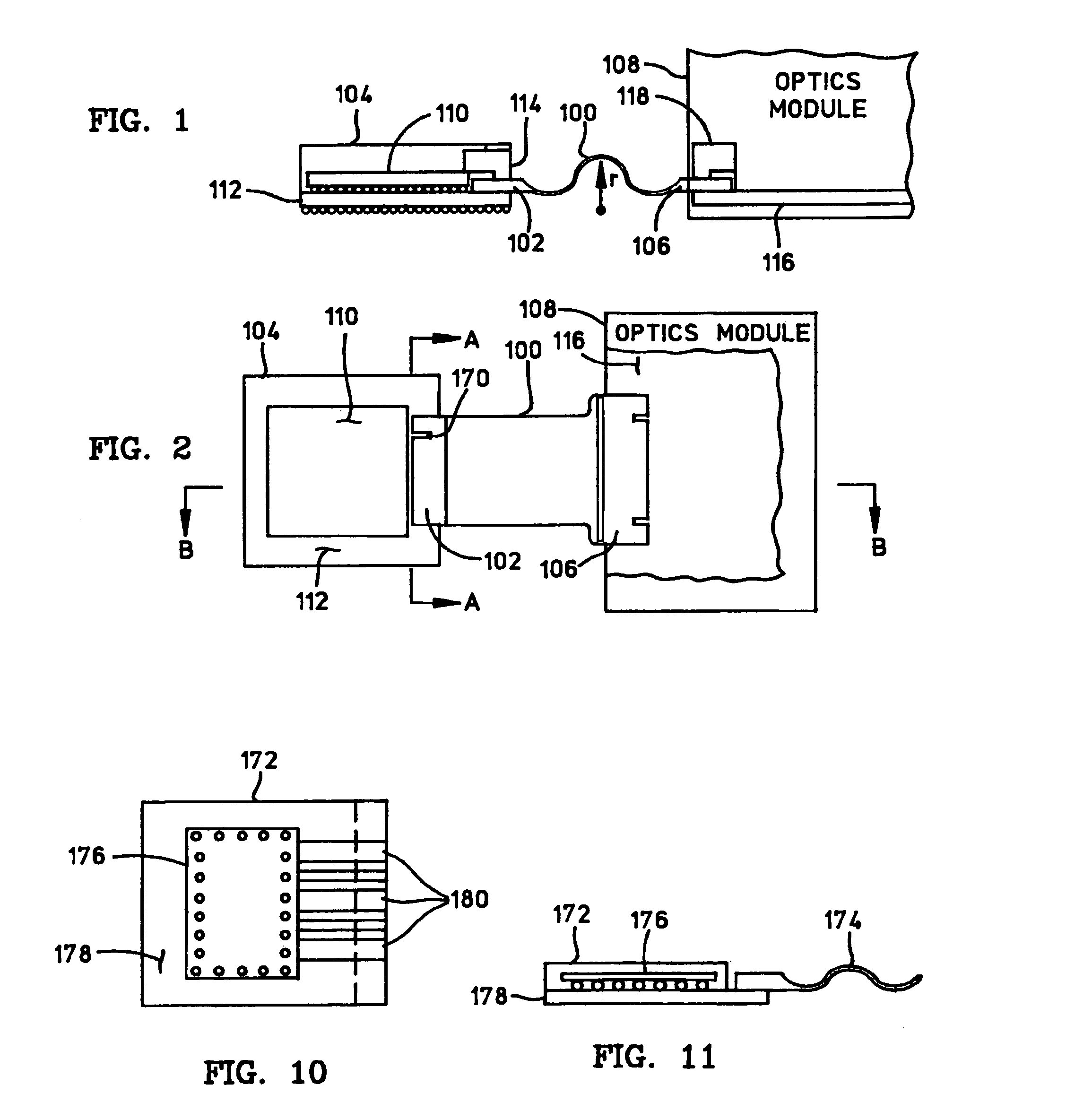
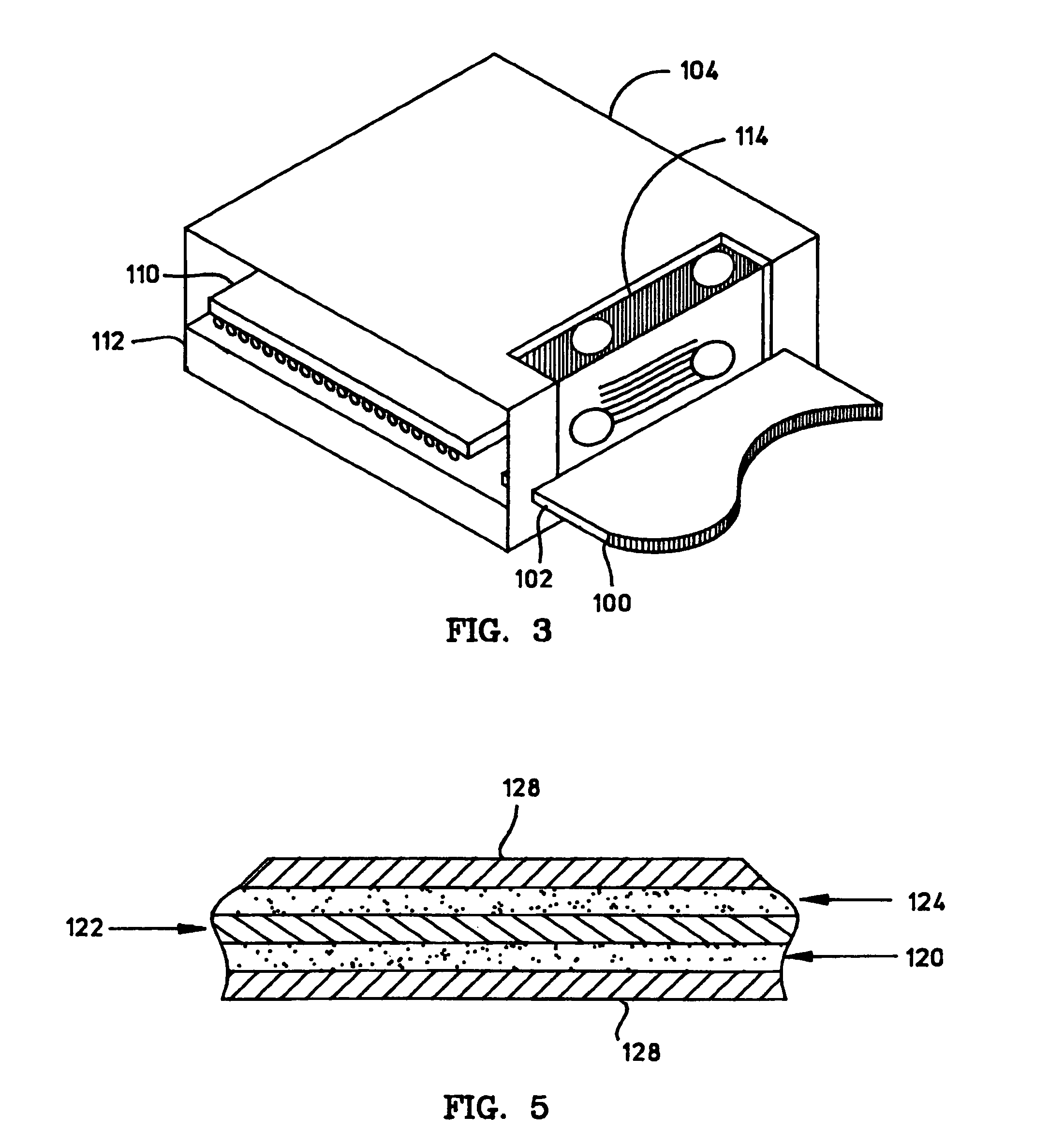
[0031]The particular implementations shown and described herein are illustrative of the invention and its best mode and are not intended to otherwise limit the scope of the invention in any way. Indeed, for the sake of brevity, conventional RF and microwave transmission line design techniques, flip chip and ball grid array design considerations, substrate interconnect and via design techniques, and manufacturing techniques such as laminating, metal deposition, etching, and the like may not be described in detail herein. In addition, various electronic devices, system components, or modules may be referred to herein as example components to which a flexible interconnect cable may be connected. In practice, the specific type of device, circuit, chip, package, module, circuit board, or component can vary from application to application.

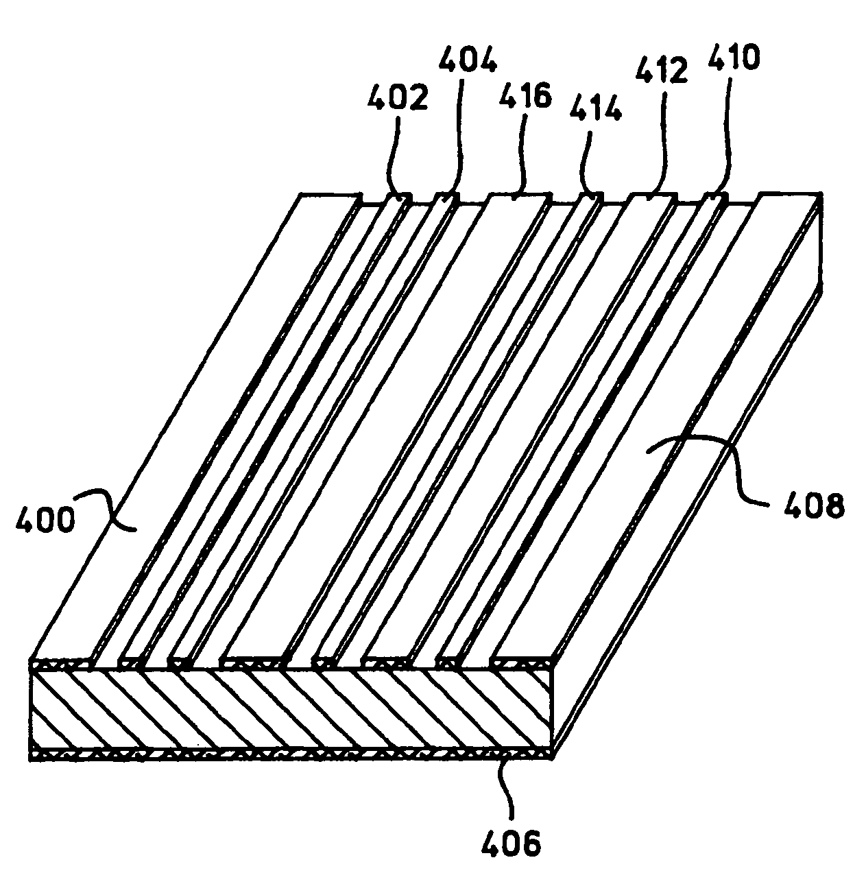
[0032]The present invention provides a flexible electrical interconnect cable having a transmission line structure that is capable of propagating high s...


PUM


Abstract

A high speed flexible interconnect cable includes a number of conductive layers and a number of dielectric layers. Conductive signal traces, located on the conductive layers, combine with the dielectric layers to form one or more high speed electrical transmission line structures. The transmission line structure may be realized as a grounded coplanar waveguide structure, a microstrip structure, a stripline structure, or the like. The cable can be coupled to destination components using a variety of connection techniques, e.g., direct bonding to a circuit substrate, direct soldering to a flip chip, mechanical attachment to a component, or integration with a circuit substrate. The cable can also be terminated with any number of known or standardized connector packages, e.g., SMA, GPPO, or V connectors.

Description

CROSS-REFERENCE TO RELATED APPLICATIONS[0001]This application claims priority of U.S. patent application Ser. No. 10 / 107,667, filed Mar. 26, 2002, titled “FLEXIBLE INTERCONNECT CABLE WITH HIGH FREQUENCY ELECTRICAL TRANSMISSION LINE”, now U.S. Pat. No. 6,797,891, which claimed priority of U.S. provisional patent application Ser. No. 60 / 365,696 filed Mar. 18, 2002 via United States Express Mail (label number EV-086138233-US), titled “FLEXIBLE INTERCONNECT CABLE WITH HIGH FREQUENCY ELECTRICAL TRANSMISSION LINE,” the content of which is incorporated by reference herein.[0002]The subject matter of this application is related to the subject matter of U.S. patent application Ser. No. 10 / 107,661, titled “FLEXIBLE HIGH FREQUENCY INTERCONNECT CABLE INTEGRATED WITH A CIRCUIT SUBSTRATE,” now abandoned, and U.S. patent application Ser. No. 10 / 107,662, titled “HIGH FREQUENCY SIGNAL TRANSMISSION FROM THE SURFACE OF A CIRCUIT SUBSTRATE TO A FLEXIBLE INTERCONNECT CABLE,” both filed Mar. 26, 2002. Th...

Claims


Application Information

Patent Timeline
Patent Type & Authority Patents(United States)
IPC IPC(8): H01P3/08
CPCH01P3/006H05K1/0219H05K1/0393H05K1/147H05K3/222H05K2201/09236H05K2201/09727H01L2224/16227H01L2224/32225H01L2224/73204H01L2224/73253H01L2924/15311H01L2924/00014H01L2924/00011H01L2224/0401H01L2224/16225H01L2924/00
Inventor BLAIR, JAMES LEROYSCHREIBER, OSWIN M.SMITH, JEFFREY THOMAS
Owner QUALCOMM INC
Why Eureka
Try Eureka