Eureka AIR delivers breakthrough ideas for toughest innovation challenges, trusted by R&D personnel around the world.

Laser oscillator

a laser oscillator and laser technology, applied in laser details, excitation process/apparatus, active medium materials, etc., can solve the problems of increasing running costs, phtocatalytic layer is scarcely expected to have a function of cleaning the optical component, and organic matter contaminating the optical component is not effectively decomposed and removed, so as to reduce the labor for maintenance of the optical component, prevent contamination, and effectively decompose and remov

Inactive Publication Date: 2006-12-12
FANUC LTD
View PDF14 Cites 2 Cited by
  • Summary
  • Abstract
  • Description
  • Claims
  • Application Information

AI Technical Summary

Benefits of technology

[0009]An object of the present invention is to effectively decompose and remove rare organic matter such as oil mist contained in an ambient gas around an optical component of a laser oscillator so as to prevent contamination and deterioration of the optical component thereby reducing labor for maintenance of the optical component and running cost of the laser oscillator and also reducing deterioration of quality of a laser beam.
[0011]Ultraviolet ray generated by the laser pumping can be utilized for exciting the photocatalyst. For effectively utilizing the ultraviolet ray, it is advantageous to arrange the photocatalyst is arranged at a region to which the ultraviolet ray is directly irradiated.
[0015]According to the present invention, the organic matter such as oil mist contained in an ambiance of the optical component of the laser oscillator is effectively decomposed and removed by photocatalysis of the photocatalyst such as titanium oxide arranged in the vicinity of the optical component, to greatly reduce contamination of the optical component by the organic matter.
[0019]Thus, the photocatalyst arranged in the vicinity of the optical component, which is excited by ultraviolet ray generated by the laser pumping, decomposes the organic matter such as oil mist contained in the ambient gas in the vicinity of the optical component to reduce contamination of the optical component.

Problems solved by technology

Therefore, it is necessary to often lean the optical component 4 or change the optical component 4 with a new one to cause increase of running cost.
Organic matter such as oil mist contained as minor component in a large mount of gas laser medium circulating at high speed hardly react with the photocatalytic layer, so that the organic matter which contaminates the optical component is not effectively decomposed and removed.
Further, since the phtocatalytic layer is arranged remote from the optical component, the phtocatalytic layer is scarcely expected to have a function of cleaning the optical component.

Method used


Image

  • Laser oscillator
  • Laser oscillator
  • Laser oscillator

Examples


Embodiment Construction

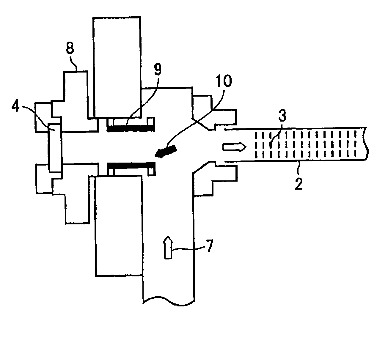
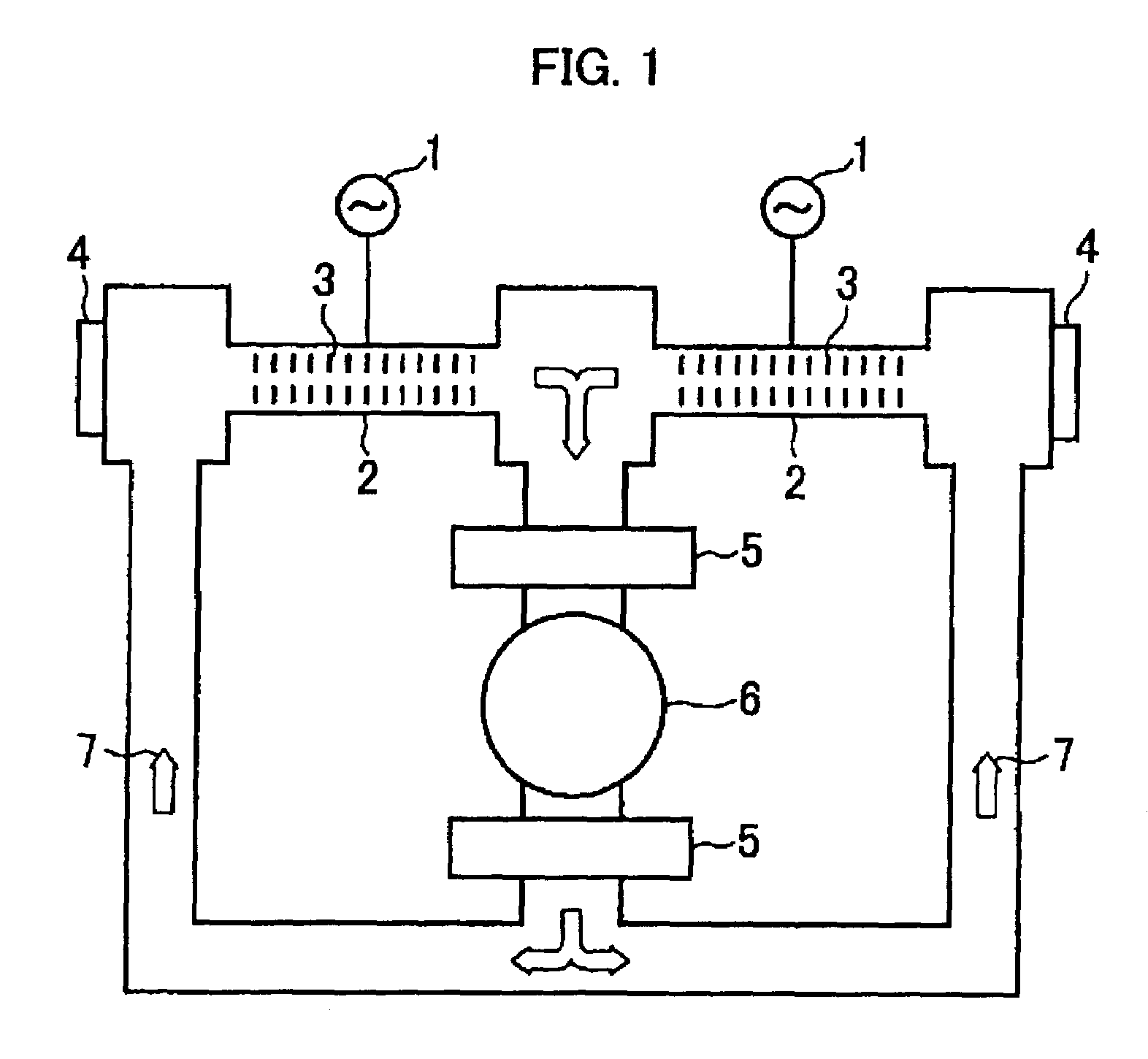
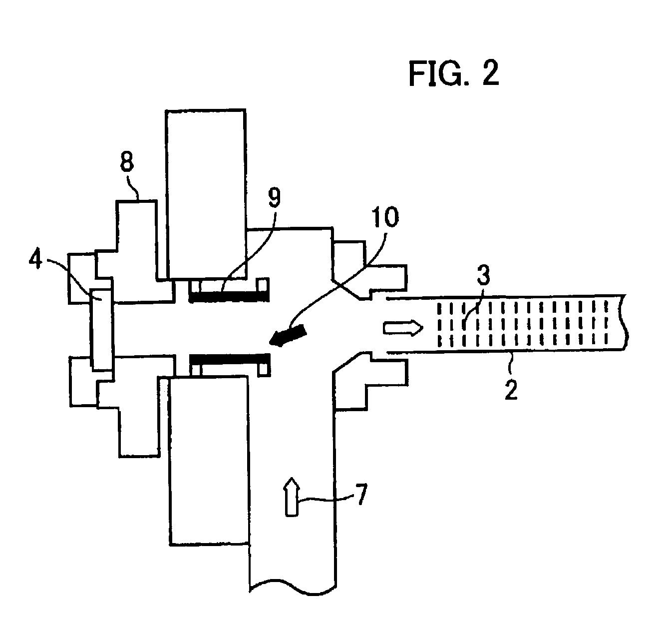
[0025]FIGS. 1 and 2 schematically show a gas laser oscillator using gas laser medium as an example of a laser oscillator according to the present invention. In the following description, the same reference numeral is assigned to an element of the laser oscillator having the same or equivalent function.

[0026]In FIG. 1, an RF (radio frequency) alternating current power source 1 is connected with electrodes (not shown) of each electric discharge tube 2. The electric discharge tubes 2 are arranged between resonator mirrors 4 constituting a laser resonator, one of which is an output mirror and the other of which is a rear mirror. As shown in FIG. 2, the resonator mirror 4 as an optical component of the laser oscillator is retained by an optical component retaining mechanism 8. As shown in FIG. 1, the electric discharge tubes 2 are incorporated in a circulating path of gas laser medium 7 including heat exchangers 5 and a blower 6, through which the gas medium 7 flows at high speed. The he...


PUM


Abstract

A laser oscillator capable of preventing contamination of optical components by organic matter such as oil mist. Gas laser medium in an optical resonator constituted by optical components is pumped by an electric discharge generated in an electric discharge tube to produce a laser beam. The gas medium flows at high speed in the electric discharge tube incorporated in a circulating path including a blower. A part of lubrication oil of the blower is evaporated and mixed into the gas medium. Since the optical components are cooled by retaining mechanisms to prevent temperature rise of the components and a gas stagnation occurs between the optical component and the electric discharge tube, the evaporated oil mist tends to be congealed and adhered to a surface of the optical component. A photocatalyst arranged in the vicinity of the optical component effectively decomposes and removes the oil mist.

Description

BACKGROUND OF THE INVENTION[0001]1. Field of the Invention[0002]The present invention relates to a laser oscillator for use in laser machining, medical treatment, illumination, communication, etc. and in particular to a laser oscillator having a function of decomposing organic matter such as oil mist in the oscillator by photocatalysis, to reduce contamination of optical components by the organic matter.[0003]2. Description of Related Art[0004]In general, there exists vaporized organic matter such as oil mist in an ambience around optical components of a laser oscillator for various causes. The vaporized organic matter is congealed and adhered to surfaces of the optical components which are cooled forcedly, and the congealed organic matter absorbs a laser beam to lower an output power of the laser beam and generates heat to deteriorate or distort the optical components to lower quality of the laser beam.[0005]FIG. 4 is a partial cross-section of a gas laser oscillator in the vicinit...

Claims


Application Information

Patent Timeline
IPC IPC(8): H01S3/22H01S3/03H01S3/034H01S3/036
CPCH01S3/03H01S3/034H01S3/0346H01S3/036
Inventor EGAWA, AKIRAANDO, MINORUWATANABE, TAKESHI
Owner FANUC LTD
Why Eureka
Eureka Blog
Learn More