Permselective membrane module

a membrane module and selective technology, applied in the field of selective membrane modules, can solve the problems of increasing reducing the separation performance of the module, so as to prevent the pressure loss of the feed liquid, reduce the cost, and simplify the membrane module

Inactive Publication Date: 2006-12-19
TOYO TOYOBO CO LTD
View PDF20 Cites 40 Cited by
  • Summary
  • Abstract
  • Description
  • Claims
  • Application Information

AI Technical Summary

Benefits of technology

[0013]The present invention provides a permselective membrane module comprising i) two permselective membrane elements formed of hollow fibers arranged substantially in parallel and bundled together and ii) a container, the two elements being arranged in the container longitudinally of the hollow fibers, wherein the respective elements comprise i) a feed tube disposed longitudinally of the hollow fibers and ii) a hollow fiber bundle covering the outer surface of the feed tube, the feed tube having a number of holes therein, and the hollow fibers having one end closed and the other end opened, wherein the feed tubes of the two elements communicate with each other via a connecting tube to form a conduit having one end opened and the other end closed, and wherein the container comprises i) an inner wall surrounding the two elements with a space, ii) a feed port provided at one end of the container in communication with the opened end of the conduit, iii) a permeate-liquid outlet facing the open end of the hollow fiber bundle of each element and extending through the con

Problems solved by technology

This phenomenon is called “nestling” that increases the pressure loss of the feed liquid and thereby lower the separation performance of the module.
However, the thus constructed reverse osmosis membrane module is likely to cause too much pressure loss due to the friction resistance generated on the tube inner wall, since the module is of a double tubular

Method used


Image

  • Permselective membrane module
  • Permselective membrane module
  • Permselective membrane module

Examples


embodiment 1

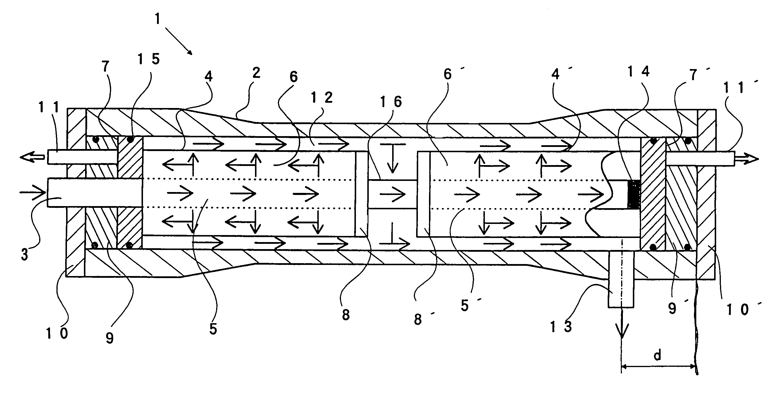
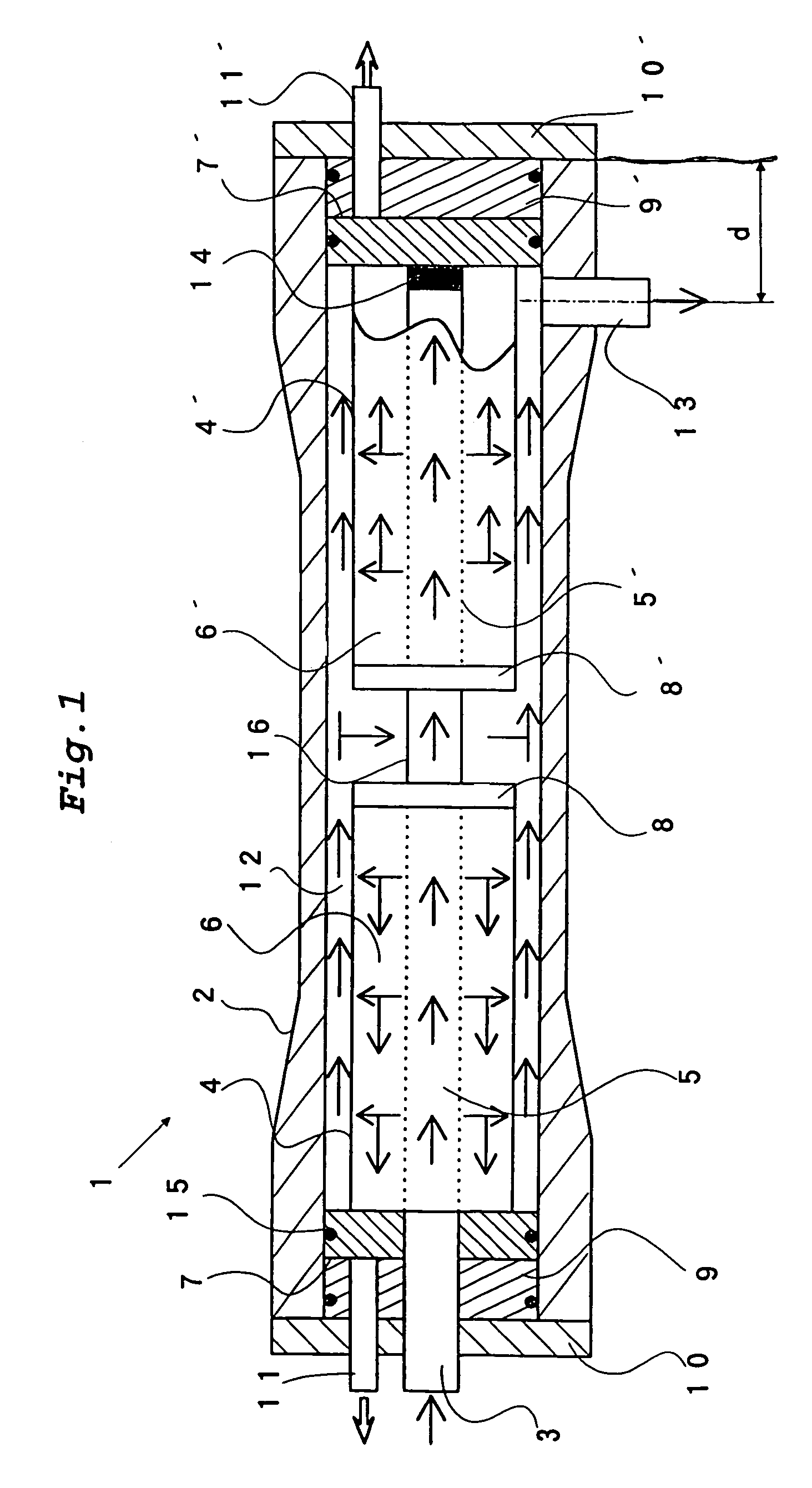
[0024]The first embodiment of the present invention will be described with reference to FIG. 1. FIG. 1 is a schematic view of a permselective membrane module 1 of the first embodiment.

[0025]The module 1 of the first embodiment comprises first and second permselective membrane elements 4, 4′ made of Hollow fibers, each element being inserted from the opposite ends of a cylindrical pressure vessel 2 and then longitudinally aligned such that deflector blocks 8, 8′ be opposed to each other. An inner connecting tube 16 is provided between the deflector blocks 8, 8′ of the elements 4, 4′. Via the inner connecting tube 16, feed tubes 5, 5′ of the first and second elements 4, 4′ are connected at the central portion of the cylindrical pressure vessel 2. The feed tubes 5, 5′ comprise a number of holes for communicating the feed tubes with the elements 4, 4′, respectively. A plug 14′ closes the end of a tube sheet 7′ of the feed tube 5′ of the second element 4′. Attached at the opposite ends o...

embodiment 2

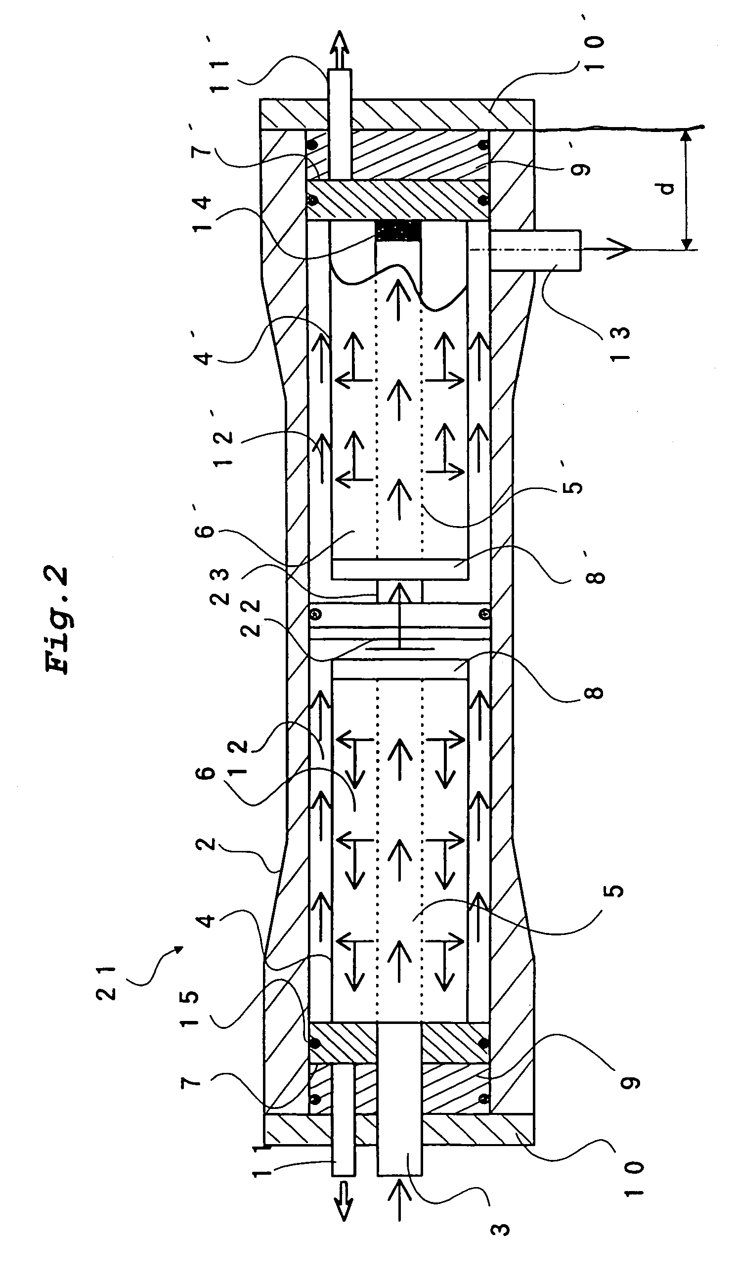
[0035]The second embodiment of the present invention will be described with reference to FIG. 2. FIG. 2 schematically shows a permselective membrane module 21 of hollow fibers according to the present embodiment. The same parts as in the previous embodiment are denoted by the same reference numerals, and the explanations therefor are omitted.

[0036]The module 21 of the second embodiment employs the following features in the module of the first embodiment, that is, one end of the feed tube 5 of the first element 4 is sealed with a deflector block 8. Further, the second embodiment employs an inner support plate 22 that is provided between the first and second elements 4, 4′ in lieu of the inner connecting pipe 16, so that the inner support plate 22 is connected to the feed tube 5′ by an inner connecting tube 23.

[0037]The feed liquid is fed into the feed tube 5 of the first element 4 via the feed port 3. Since one end of the feed tube 5 is closed by the deflector block 8, the feed liqui...

example 1

[0046]Example 1 was conducted to evaluate the separation performance of the hollow fiber membrane module 1 of the first embodiment.

Example 1-(1)

[0047]In Example 1-(1), brackish water was used as a feed liquid. The operating conditions were that the pressure applied was 30 kg / cm2, and the recovery ratio was 75%.

[0048]The test results of Example 1-(1) is shown in Table 1 below.

[0049]

TABLE 1Permeate FluxDifferential Pressure(m3 / day)(kg / cm2)Example 1-(1)830.13Example 2-(1)750.18Comp. Exmp. 1-(1)690.19Example 1-(2)540.30Example 2-(2)490.35Comp. Exmp. 1-(2)450.47

[0050]As seen from Table 1, the differential pressure in Example 1-(1) was low, i.e., 0.13 kg / cm2, and the permeate flux through the module was 83 m3 / day, which means that the membrane separation was conducted efficiently.


PUM

PropertyMeasurementUnit
Pressureaaaaaaaaaa

Abstract

Disclosed is a permselective membrane module comprising i) two permselective membrane elements formed of hollow fibers arranged substantially in parallel and bundled together and ii) a container, the two elements being arranged in the container longitudinally of the hollow fibers, wherein the respective elements comprise i) a feed tube disposed longitudinally of the hollow fibers and ii) a hollow fiber bundle covering the outer surface of the feed tube, the feed tube having a number of holes therein, and the hollow fibers having one end closed and the other end opened, wherein the feed tubes of the two elements communicate with each other via a connecting tube to form a conduit having one end opened and the other end closed, and wherein the container comprises i) an inner wall surrounding the two elements with a space, ii) a feed port provided at one end of the container in communication with the opened end of the conduit, iii) a permeate-liquid outlet facing the open end of the hollow fiber bundle of each element and extending through the container wall, and iv) a non-permeated fluid discharge outlet communicating with the gap between the container and the outer surface of each element and extending through the container wall.

Description

DETAILED DESCRIPTION OF THE INVENTION[0001]The present invention concerns a permselective membrane module made of hollow fibers and used for desalination.PRIOR ART[0002]There are classified several types of permselective membranes according to the size of a substance to be separated. Examples of such membranes are ultrafilters or microfilters for separating colloids, proteins or the like, nano-filters for separating low molecular organic matters such as agricultural chemicals or the like, and reverse osmosis membranes used for separation of ions. The reverse osmosis membranes are those used under a higher pressure than the osmotic pressure of liquid to be treated (hereinafter, “liquid to be treated” is referred to as “feed liquid”).[0003]The membranes can also be classified into flat type, tubular type, spiral type and hollow fiber type in view of shape. Among them, the hollow fiber type can be used without support materials usually required in the flat type, the tubular type or the...

Claims


Application Information

Patent Timeline
IPC IPC(8): B01D63/00B01D61/00B01D63/04
CPCB01D63/043B01D63/024B01D2313/10B01D2313/13Y02A20/131
Inventor KATSUBE, MIKIONITA, KAZUHIDESEKINO, MASAAKI
Owner TOYO TOYOBO CO LTD
Why Eureka
Try Eureka