Method of sterilizing a medical device

a technology of medical devices and catheters, applied in the field of medical devices, can solve the problems of reducing the trackability and crossability of the catheter in the patient's vasculature, affecting the treatment effect, so as to increase the wall thickness of the balloon, and avoid significant degradation of polymeric materials.

Inactive Publication Date: 2006-12-19
ABBOTT CARDIOVASCULAR
View PDF16 Cites 74 Cited by
  • Summary
  • Abstract
  • Description
  • Claims
  • Application Information

AI Technical Summary

Benefits of technology

[0006]This invention is directed to a method of sterilizing a medical device component, such as a catheter balloon or shaft, in which an electron beam (i.e., e-beam) is applied to the component in an evacuated or inert gas-filled container. The method of the invention allows for electron beam sterilization without significant degradation of the component polymeric material. It is believed that by minimizing the presence of air during the electron beam sterilization, the method inhibits or prevents the formation of reactive oxygen and nitrogen radicals which would otherwise form from the action of the electron beam radiation on air. Another aspect of the invention is a medical device component, e-beam sterilized according to a method of the invention. A variety of medical device components can be sterilized by the method of the invention, and particularly intracorporeal devices for therapeutic or diagnostic purposes, such as balloon catheters, catheter shafts and balloons, stent covers, and vascular grafts. In one embodiment, the device component is configured to be pressurized or expanded during use, and the method of the invention provides such a device component with a rupture pressure that is not significantly decreased due to electron beam sterilization. Although discussed primarily in terms of a balloon for a balloon catheter, the invention should be understood to include other medical devices. The terminology “medical device component” should be understood to include an independent, complete item such as a vascular graft or balloon catheter, or alternatively, a part of a larger device such as a balloon or a shaft of a balloon catheter.
[0007]In one embodiment, the balloon itself, which has typically already been secured to a catheter shaft to form an assembled balloon catheter, is evacuated and / or filled with an inert gas before the electron beam sterilization. In a presently preferred embodiment, the balloon is purged by applying a vacuum to evacuate the balloon and back filling the evacuated balloon with an inert gas. Thus, the air which would have been present inside the balloon and catheter shaft interior is removed and replaced with an inert gas before the electron beam sterilization. As a result, the degradation of the balloon polymeric material due to the electron beam sterilization is minimized. In a presently preferred embodiment, the balloon catheter is purged before being placed inside the container, and before the container is similarly purged by evacuating the container and back filling the container with an inert gas. However, in an alternative embodiment, the balloon catheter is purged after being placed in the container.
[0009]In a presently preferred embodiment, the container is filled with inert gas so that the container has a positive pressure which thus prevents or inhibits air leaking into the container in the event that pinholes develop in the container. The inert gas consequently prevents degradation of the balloon polymer during or shortly after the electron beam application and the attendant loss of sterilization if pin holes develop in the container during storage of the catheter. However, in an alternative embodiment, the container is merely evacuated by applying a vacuum to the container and sealing the container, without necessarily filling the container with an inert gas before and the container sealed with the medical device component therein. The container and balloon are evacuated by applying a vacuum to an interior thereof to thereby reduce the internal pressure therein to less than the ambient pressure. For example, the absolute pressure in the evacuated container is typically not greater than about 50 mTorr. After filling with the inert gas, the pressure inside the inert gas-filled container is typically not less than about 1 atm (760 Torr). In a presently preferred embodiment, the container (with the balloon catheter therein) is purged inside a vacuum chamber. Thereafter, the container may be sealed inside the evacuated or inert gas-filled vacuum chamber if the vacuum chamber contains a sealer, or transferred to another vacuum chamber containing a sealer. Alternatively, the purged container may be removed from the vacuum chamber and maintained in an open end-up orientation and sealed outside the vacuum chamber. Inert gas such as argon is heavier than air and will thus prevent air going into the argon-filled container when the container is held with the open end of the container up in an air-filled environment prior to sealing the container.
[0010]A catheter polymeric balloon sterilized according to the method of the invention has minimal degradation of the polymer, and consequently, a minimal decrease in rupture pressure due to the sterilization. After the electron beam sterilization according to the method of the invention, the balloon has a mean rupture pressure which is not significantly less than (i.e., not more than 5% to about 25% less than, and preferably not more than about 10% to about 15% less than) the rupture pressure of the balloon before the electron beam sterilization of the method of the invention. Furthermore, the balloon preferably has a high fatigue resistance, i.e., cycles to failure, which is not significantly less than (i.e., not more than about 5% to about 10% less than) the fatigue resistance of the balloon before the electron beam sterilization of the method of the invention. After accelerated aging to simulate shelf life of the balloon in which the balloon is aged at about 45° C. to about 65° C. for about 1 to about 3 weeks, a balloon sterilized according to the method of the invention in an evacuated or inert gas-filled container has a mean rupture pressure which is significantly higher than (i.e., more than about 15% to about 25% higher than) the rupture pressure of a balloon electron beam sterilized in the presence of air although otherwise similarly aged and sterilized, and a fatigue resistance which is significantly higher than (i.e., more than about 1000% to about 1500% higher than) the fatigue resistance of the balloon electron beam sterilized in the presence of air.
[0013]The sterilization method of the invention avoids significant degradation of the polymeric material of the medical device component, as a result of sterilizing the medical device component in an evacuated or inert gas-filled container. Consequently, the method provides a sterilized medical device component such as a catheter balloon having a sufficiently high rupture pressure, without requiring an increase in the wall thickness of the balloon. The method thus provides for improved manufacturability of the balloon catheter, and a balloon catheter having excellent performance characteristics such as low profile and flexibility, for excellent trackability, and a desired rupture pressure and fatigue resistance. These and other advantages of the invention will become more apparent from the following detailed description and accompanying exemplary drawings.

Problems solved by technology

Substantial, uncontrolled expansion of the balloon against the vessel wall can cause trauma to the vessel wall.
One difficulty has been sterilizing polymeric materials which degrade substantially in response to a conventional sterilization method.
Increasing the wall thickness of such balloons to provide an acceptably high rupture pressure increases the profile and stiffness of the balloon, and consequently decreases the trackability and crossability of the catheter in the patient's vasculature.

Method used


Image

  • Method of sterilizing a medical device
  • Method of sterilizing a medical device
  • Method of sterilizing a medical device

Examples


Embodiment Construction

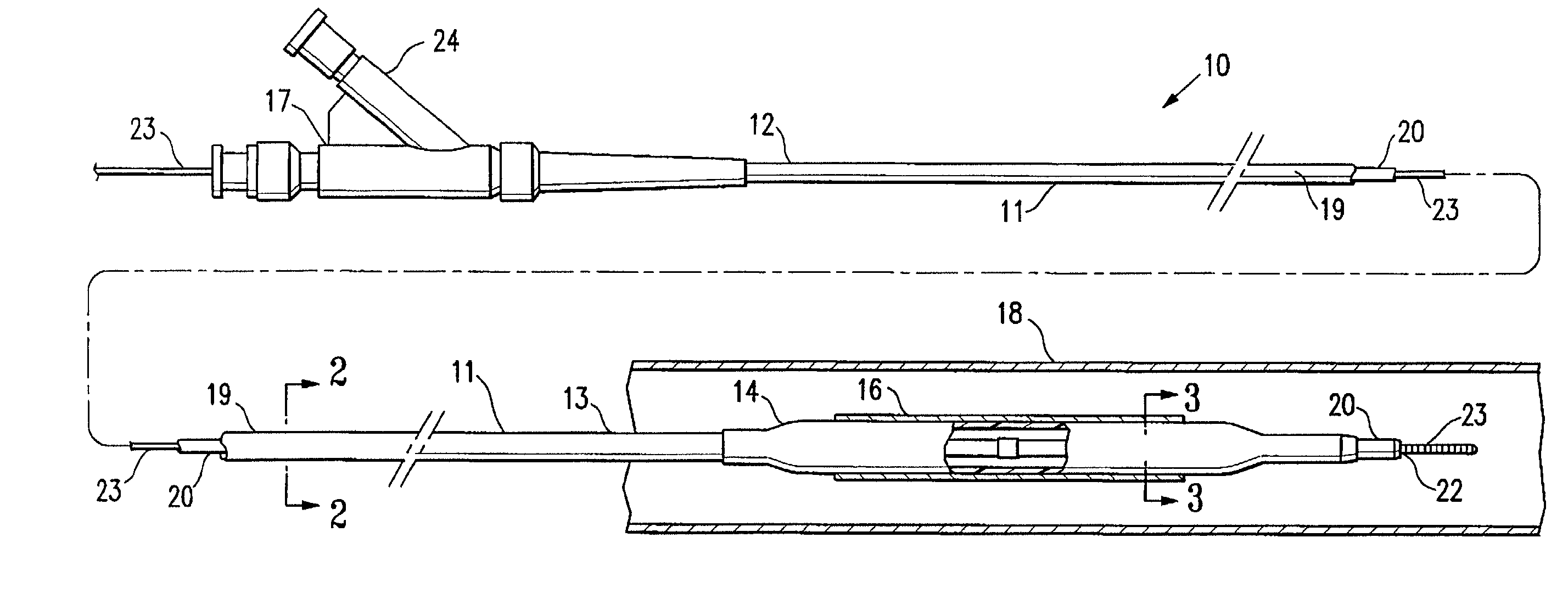
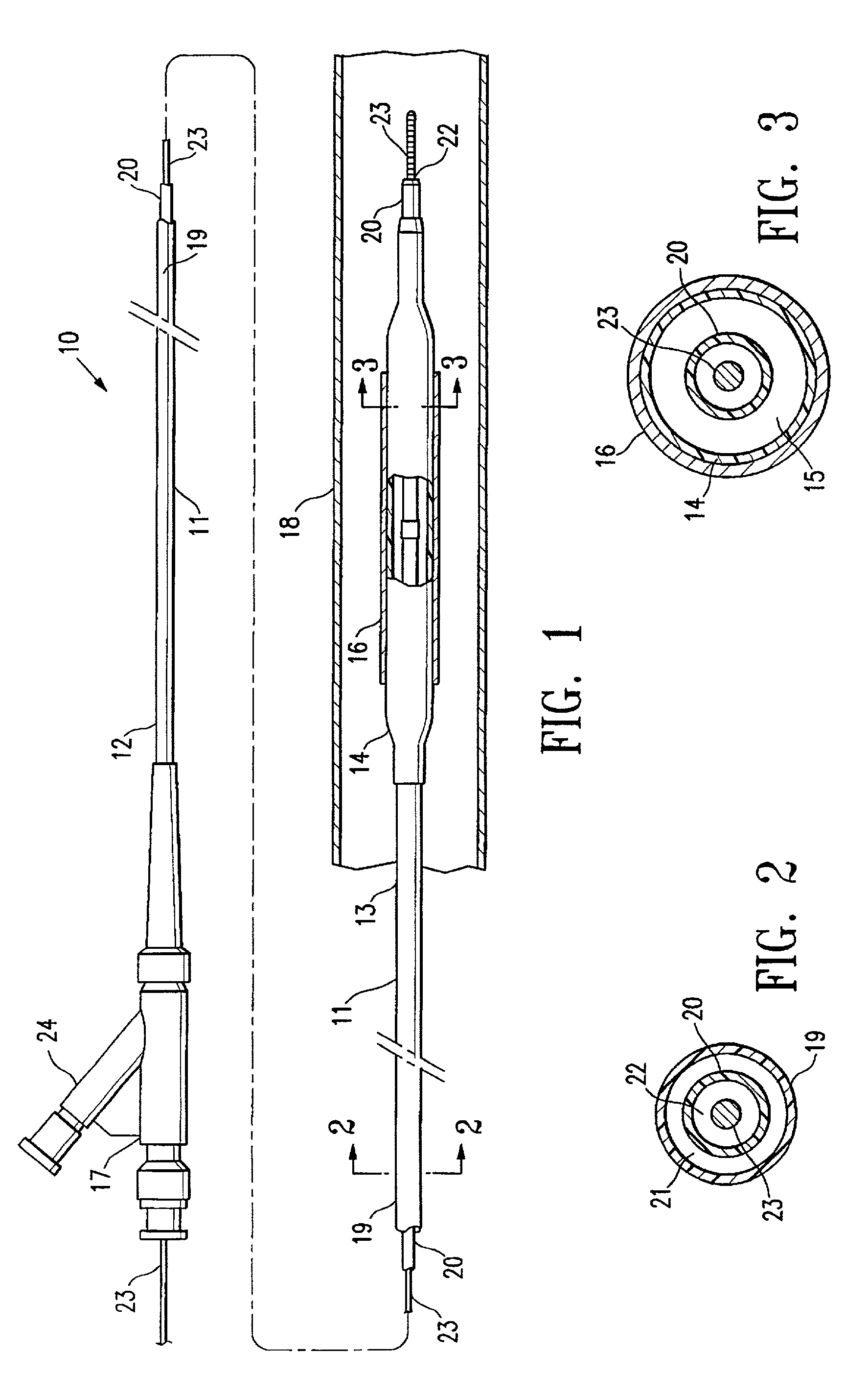
[0020]FIG. 1 illustrates an over-the-wire type stent delivery balloon catheter 10 embodying features of the invention. Catheter 10 generally comprises an elongated catheter shaft 11 having a proximal end 12, a distal end 13, and an inflatable balloon 14 on a distal shaft section. An expandable stent 16 is mounted on balloon 14 for implanting in the patient's body lumen 18. In the embodiment illustrated in FIG. 1, the shaft 11 comprises an outer tubular member 19 and an inner tubular member 20. As best shown in FIGS. 2 and 3, illustrating transverse cross sections of the catheter 10 shown in FIG. 1, taken along lines 2—2 and 3—3, respectively, outer tubular member 19 defines an inflation lumen 21, and inner tubular member 20 disposed within the outer tubular member lumen 21 defines a guidewire lumen 22 configured to slidingly receive a guidewire 23. Inflatable balloon 14 is disposed on a distal section of catheter shaft 12, having a proximal end sealingly secured to the distal end of...


PUM

PropertyMeasurementUnit
pressuresaaaaaaaaaa
pressureaaaaaaaaaa
pressureaaaaaaaaaa

Abstract

A method of sterilizing a medical device component, such as a catheter balloon, in which an electron beam (i.e., e-beam) is applied to the component in an evacuated or inert gas-filled container. The method of the invention allows for electron beam sterilization without significant degradation of the component polymeric material. In one embodiment, the device component is configured to be pressurized or expanded during use. The method of the invention provides a component with a rupture pressure that is not significantly decreased due to electron beam sterilization. Another aspect of the invention is a medical device component, e-beam sterilized according to a method of the invention. A variety of medical device components can be sterilized by the method of the invention, and particularly intracorporeal devices for therapeutic or diagnostic purposes, such as balloon catheters, catheter shafts and balloons, stent covers, and vascular grafts.

Description

BACKGROUND OF THE INVENTION[0001]This invention relates generally to medical devices, and particularly to balloon catheters, including angioplasty and stent delivery balloon catheters.[0002]In percutaneous transluminal coronary angioplasty (PTCA) procedures, a guiding catheter is advanced until the distal tip of the guiding catheter is seated in the ostium of a desired coronary artery. A guidewire, positioned within an inner lumen of a dilatation catheter, is first advanced out the distal end of the guiding catheter into the patient's coronary artery until the distal end of the guidewire crosses a lesion to be dilated. Then the dilatation catheter having an inflatable balloon on the distal portion thereof is advanced into the patient's coronary anatomy, over the previously introduced guidewire, until the balloon of the dilatation catheter is properly positioned across the lesion. Once properly positioned, the dilatation balloon is inflated with liquid one or more times to a predeter...

Claims


Application Information

Patent Timeline
Patent Type & Authority Patents(United States)
IPC IPC(8): A61L2/08A61F2/958
CPCA61L2/087A61L2202/24A61M25/10
Inventor LEE, JEONG S.WANTINK, KENNETH L.
Owner ABBOTT CARDIOVASCULAR
Why Eureka
Try Eureka