Eureka AIR delivers breakthrough ideas for toughest innovation challenges, trusted by R&D personnel around the world.

Heat treating apparatus and heat treating method

a heat treatment apparatus and heat treatment technology, applied in the direction of manufacturing tools, process and machine control, instruments, etc., can solve the problems of in-plane temperature distribution of substrate g in heat-up period, large deviation in coating film thickness, and disadvantageous temperature of substrate g, etc., to achieve high accuracy, short time, and heat treatment

Active Publication Date: 2006-12-19
TOKYO ELECTRON LTD
View PDF6 Cites 2 Cited by
  • Summary
  • Abstract
  • Description
  • Claims
  • Application Information

AI Technical Summary

Benefits of technology

[0013]In the above-mentioned situation, it is an object of the present invention to provide heat treating apparatus and method capable of heat treatment with high accuracy in a short time when applying a designated heat treatment on a substrate mounted on a heating plate under condition that the temperature of the substrate is stabilized at a processing temperature as a target temperature. Another object of the invention is to provide heat treating apparatus and method capable of enhancing the in-plane uniformity in the temperature of the heating plate thereby applying a heat treatment with high “in-plane” uniformity on the substrate.
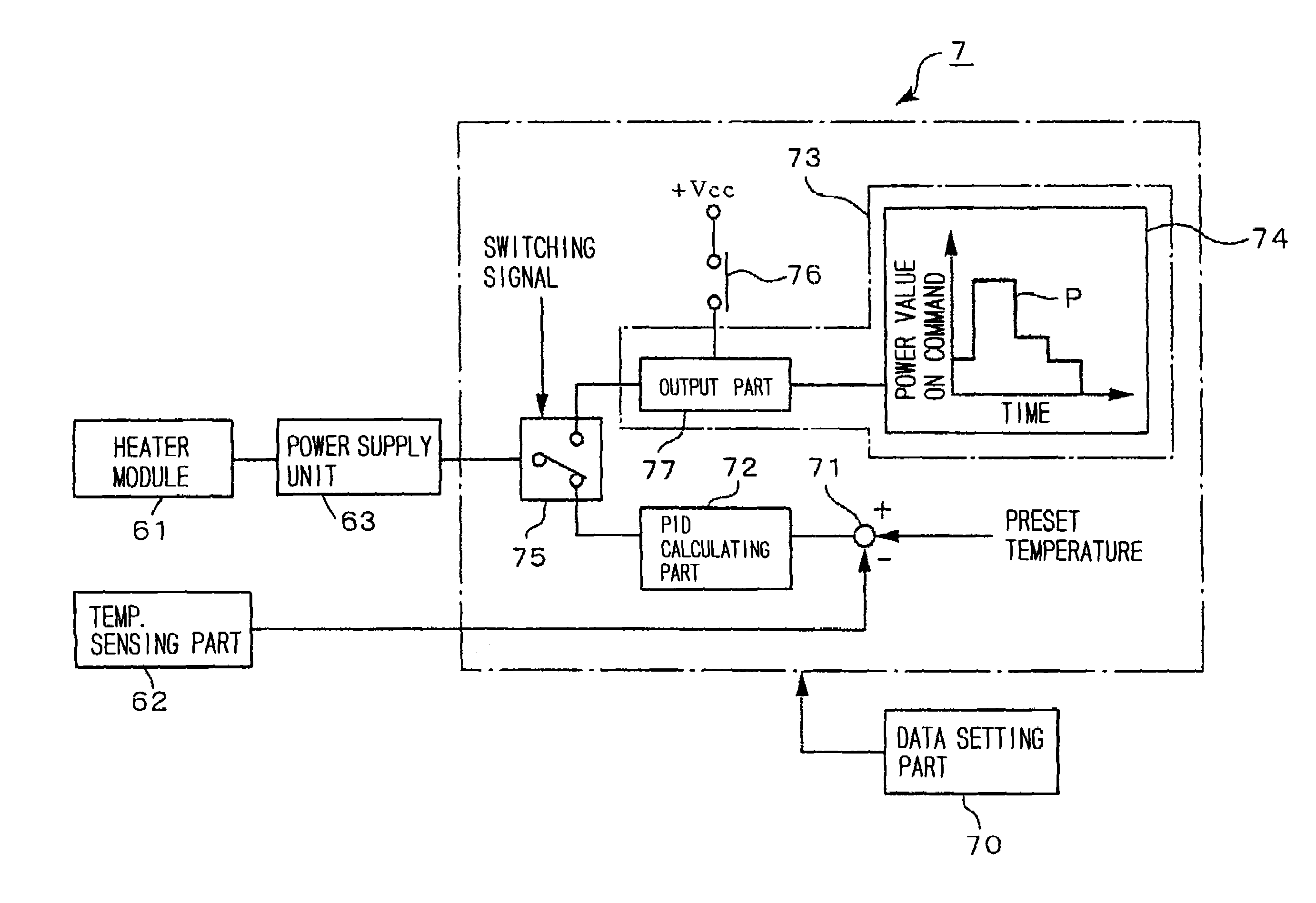
[0021]The eighth feature of the invention resides in that a heat treating apparatus comprising: a heating plate for applying a designate heat treatment to a substrate mounted on a surface of the heating plate, the heating plate being heated by heating unit generating heat on power supply; transfer unit configured to receive the substrate loaded from an outside of the apparatus and exclusively transfer the substrate to the heating plate; a temperature sensing part for detecting a temperature of the heating plate; and a regulating part for calculating an amount of power supply for the heating unit based on a difference between the temperature of the heating plate detected by the temperature sensing part and a target temperature, the regulating part further outputting a first signal corresponding to the amount of power supply calculated; a fixed-pattern output part for outputting a second signal corresponding to an amount of power supply for the heating unit based on a predetermined output pattern; and switching unit that switches a control output from an output of the regulating part to an output of the fixed-pattern output part in a period from a mounting of the substrate on the transfer unit till a mounting of the substrate on the heating plate through a transportation of the transfer unit and that switches the control output from the output of the fixed-pattern output part to the output of the regulating part at a predetermined timing since the substrate has been mounted on the heating plate, thereby compensating the operation of the regulating part derived from any disturbance in loading the substrate into the apparatus.
[0042]In this way, it is possible to restore the reduced temperature of the heating plate before mounting the substrate thereon to the original temperature quickly, whereby a heat treatment can be accomplished with high accuracy and short time. Additionally, by allocating output patterns to a plurality of heating unit respectively, it is possible to attain independent heat-up control with respect to each area of the heating plate in charge of each heating unit. Thus, since a deviation in temperatures of the whole surface of the substrate is restrained, it is possible to provide a heating operation with high “in-plane” uniformity. As a result, since such a heating operation allows the heating plate to be elevated in temperature while maintaining the high “in-plane” uniformity, it becomes possible to perform a heat treatment with high “in-plane” uniformity.

Problems solved by technology

As a result, with the overshoot of the heating plate 1 in temperature, the temperature of the substrate G may overshoot disadvantageously, as well.
In such a case, there is a possibility of producing great deviations in the thickness of coating films formed on the substrates G. In order to deal with such a disadvantage, if the responsibility of the PID control is established low so as to elevate the temperature of the heating plate 1 moderately in view of avoiding its overshoot in temperature, a long time will be required to recover the temperature of the plate 1 for the target value, also causing a disadvantage.
However, the technique disclosed in Japanese Patent Publication No. 11-74187 has the following problem.
Since the MV control does not allow the temperature difference between the peripheral area of the plate 1 and the center area to be redressed, the in-plane temperature distribution of the substrate G in its heat-up period deteriorates consequently.
Thus, it is difficult to accomplish uniform heat treatment in the surface of the substrate G, causing the evaporation rate of solvent in the coating liquid on the substrate G to be inhomogeneous in plane.
As a result, there is a worry that the film thickness of the coating film varies in the surface of the substrate.
Additionally, since it is difficult to apply uniform heat treatment on the substrates G, the film thickness of the coating film may vary among the substrates G. For the mask substrate, since it is required to have in-plane uniformity with high accuracy, such a problem becomes obvious.
However, the above-mentioned publication (No. 11-74187) does not suggest or teach a technique to dissolve such a problem.

Method used


Image

  • Heat treating apparatus and heat treating method
  • Heat treating apparatus and heat treating method
  • Heat treating apparatus and heat treating method

Examples


Embodiment Construction

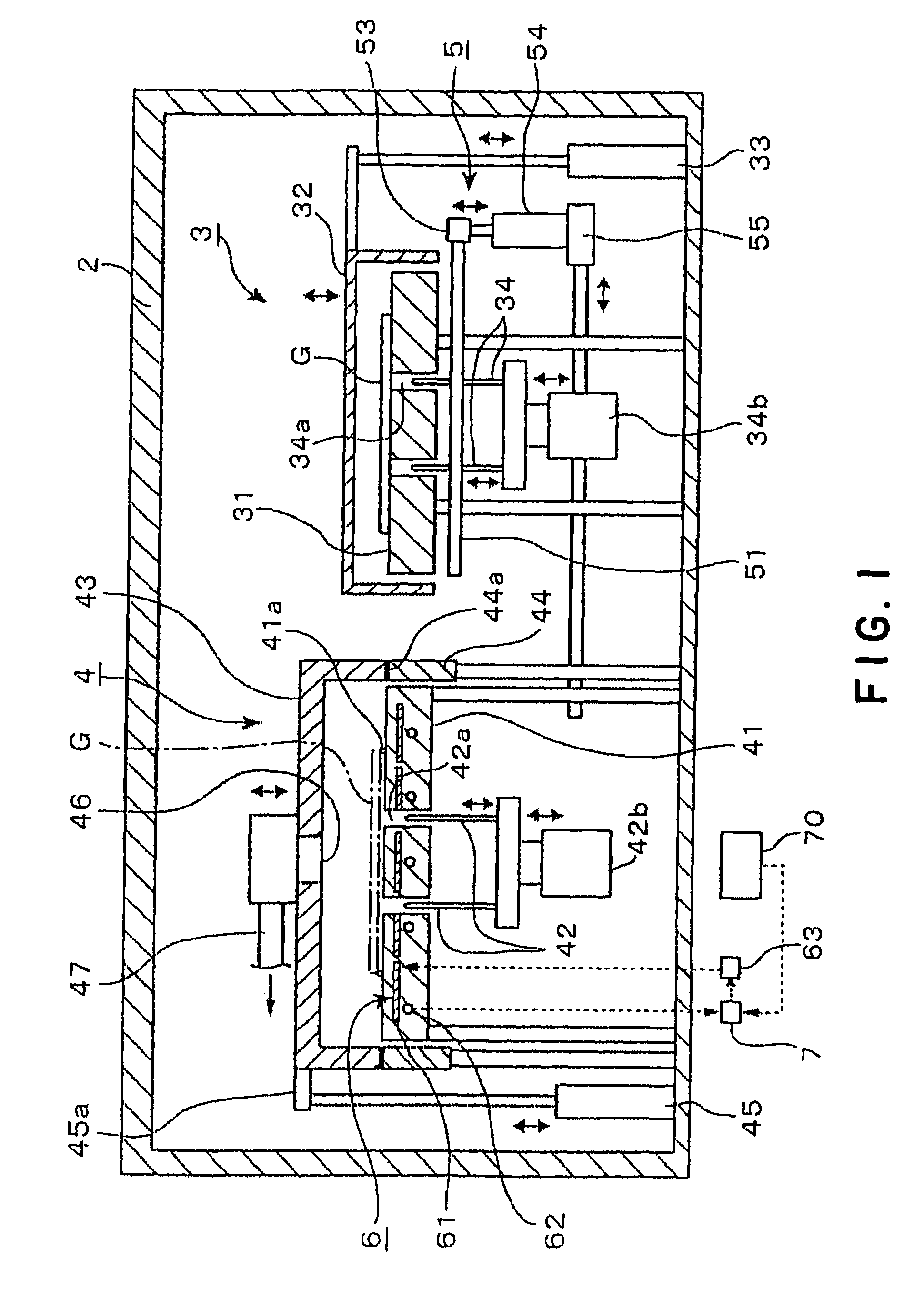
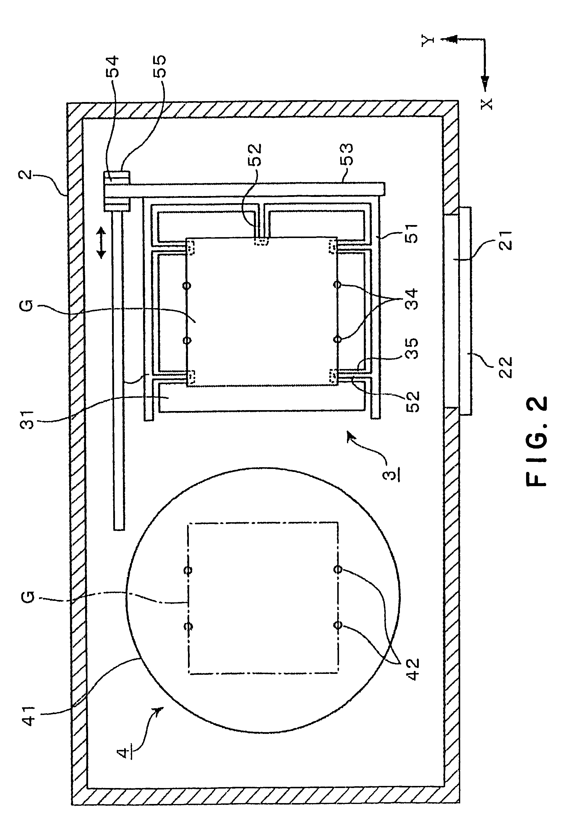
[0054]A heat treating unit forming a heat treating apparatus of an embodiment of the present invention will be described with reference to FIGS. 1 and 2. In the figures, reference numeral 2 designates a processing container forming an exterior body of the heat treating unit, in which a cooling section 3, a heating section 4 and exclusive transfer unit (i.e. transfer mechanism) 5 are arranged. The cooling section 3 is provided to apply a designated cooling process to a substrate G, such as mask substrate, while the heating section 4 is provided to apply a designated heating process to the substrate G. The transfer unit 5 is adapted so as to transfer the substrate G between the cooling section 3 and the heating section 4 exclusively.

[0055]The cooling section 3 includes a cooling plate 31 for mounting the substrate G in a predetermined mounting area and further cooling the substrate G. In the shown example, the cooling plate 31 is formed larger than the substrate G. By a not-shown cool...


PUM

PropertyMeasurementUnit
temperatureaaaaaaaaaa
surface temperatureaaaaaaaaaa
temperatureaaaaaaaaaa

Abstract

A heat treating apparatus is provided to apply a heat treatment on a substrate. Prior to the heat treatment, an exclusive transfer mechanism transfers the substrate from a cooling plate onto a heating plate for heating the substrate. Before mounting the substrate on the heating plate, the control mode for heater modules for heating the heating plate on power supply module is switched from a PID control by a regulating part in a controller of the apparatus to a MV control by a fixed-pattern output part in the controller. Next, at a predetermined timing since the substrate has been mounted on the heating plate, the MV control is switched to the PID control. Consequently, it becomes possible to quickly restore a reduce temperature of the heating plate prior to the mounting of substrate on the heating plate and also possible to quickly stabilize a so-raised temperature of the heating plate, accomplishing a heating process with high accuracy and shirt time. Accordingly, when it is required to perform a designated heat treatment on condition that a substrate is mounted on the heating plate whose temperature is stabilized to a processing temperature as a target, the heat treatment with high accuracy can be accomplished in a short time.

Description

BACKGROUND OF THE INVENTION[0001]1. Field of the Invention[0002]This invention relates to heat treating apparatus and method for heating a substrate, such as mask substrate for photomask, after applying resist liquid on the substrate or after exposing the resist liquid on the substrate and before developing the substrate.[0003]2. Background Art[0004]In the manufacturing process for semiconductor devices, a manufacturing technology called “photo lithography” is employed to form a desired resist pattern on the surface of a semiconductor. Also, for a rectangular mask substrate (reticle substrate) as an exposure mask for a semiconductor device, the lithography is used as well, where resist liquid is firstly applied on the surface of the substrate and secondly, the resulting resist film is exposed using a desired pattern and thereafter, the mask substrate is developed to form a designated resist pattern on the surface of the substrate.[0005]It is noted that the above-mentioned resist liq...

Claims


Application Information

Patent Timeline
Patent Type & Authority Patents(United States)
IPC IPC(8): H05B3/68H05B1/02G03F1/68G03F1/82G05D23/22H01L21/00H01L21/027H01L21/68H01L21/683H05B3/00H05B3/02H05B3/10H05B3/74
CPCG05D23/2231H01L21/67109H01L21/67248G05D23/1935G05D23/22
Inventor TAKEI, TOSHICHIKAKANEDA, MASATOSHI
Owner TOKYO ELECTRON LTD
Why Eureka
Eureka Blog
Learn More