Method, system and module for monitoring a power generating system

a power generating system and monitoring system technology, applied in the field of power generating systems, can solve the problems of low peak steam/power generation, poor or non-uniform combustion, and low availability

Active Publication Date: 2006-12-19
GENERAL ELECTRIC CO
View PDF3 Cites 64 Cited by
  • Summary
  • Abstract
  • Description
  • Claims
  • Application Information

AI Technical Summary

Benefits of technology

[0009]In one aspect, the present invention provides a sensing module positioned about an optical fiber cable having a long axis. The optical fiber cable includes a core that transmits light through the optical fiber. The sensing module includes a first short-period fiber grating positioned about the core. A second short-period fiber grating is positioned about the core and at a distance along the long axis with respect to the first short-period fiber grating. At least one of a long-aperiod fiber grating and a long-period fiber grating is positioned between the first short-period fiber grating and the second short-period fiber grating. A fiber cladding is positioned about the long-aperiod fiber grating and / or the long-period fiber grating. A sensing skin having a chemical gas active material is positioned about the fiber cladding.

Problems solved by technology

Poor or non-uniform combustion leads to low availability, low peak steam / power generation, low efficiency and high emissions.
Conventional industrial boiler and utility boiler controls are often based on data driven or empirical models with limited feedback from the boiler environment due to limited real-time, multi-point monitoring and sensing capabilities.
Due to non-uniform combustion, power generation oriented utility boilers or process steam generating industrial boilers tend to operate at lower efficiencies than the design limits, thus resulting in high operating and maintenance costs.
In addition, limited sensing and actuation capabilities and limited real-time information regarding boiler condition leads to solutions that are not very effective for reducing emissions or improving efficiency.
Many conventional industrial or utility boilers suffer in this context and provide only limited improvements in emission reduction and / or efficiency.
Conventional electric-based gas sensors operate at temperatures less than about 500° C. due to sensing material and / or device limitations.
The reliability of conventional electric-based gas sensors has suffered from several problems.
These gas sensors fail to operate when the environmental temperature is higher than the sensor's operating temperature.
It is also difficult to predict the gas concentration due to the temperature-dependent nonlinear sensitivity characteristics.
Additionally, electric-based gas sensors suffer from long-term stability or sensitivity degradation due to thermal effects on the electrical interfaces to supply power or transmitting signal.
Further, they are not suitable for high-voltage and explosive environments.
Finally, electric-based sensors are not suitable for multiple point gas sensing applications.
However, these devices also tend to fail at higher temperatures due to thermal effects on the electrical interfaces to supply power or a transmitting signal as well.
There is no systematic method to adjust the air and fuel flows for reducing spatial variance of emissions at a boiler's exit to reduce stack emissions.
Data-driven models such as Neural Networks and Expert Systems lack the rigor and fidelity and thereby have limited impact on efficiency because these models are dependent on data quality and are prone to data noise and inaccuracies.
Model-based optimization systems that incorporate the physics of the combustion system along with accurate and spatially dense data provided by a fiberoptic sensor array overcome the limitations of currently available boiler optimization products that rely on data limited in terms of availability, accuracy and spatial density due to the harsh environment of boiler systems and sensor capability limitations.

Method used


Image

  • Method, system and module for monitoring a power generating system
  • Method, system and module for monitoring a power generating system
  • Method, system and module for monitoring a power generating system

Examples


Embodiment Construction

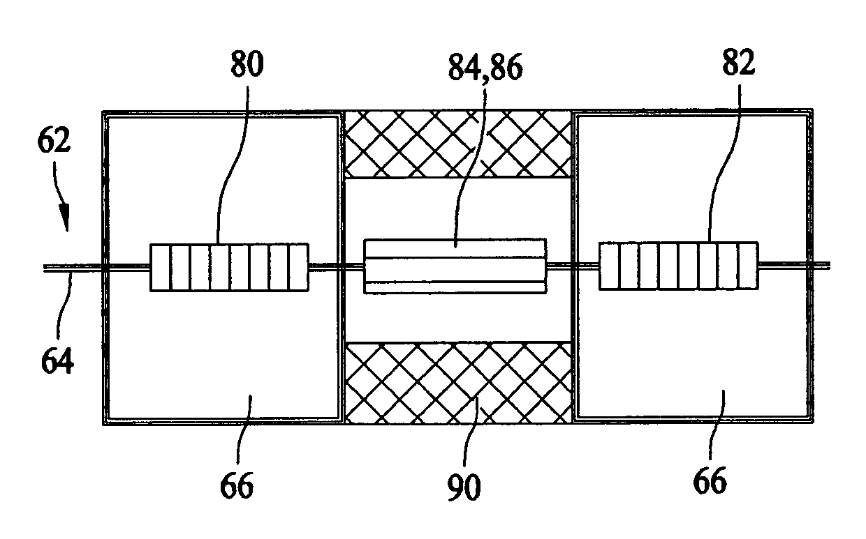
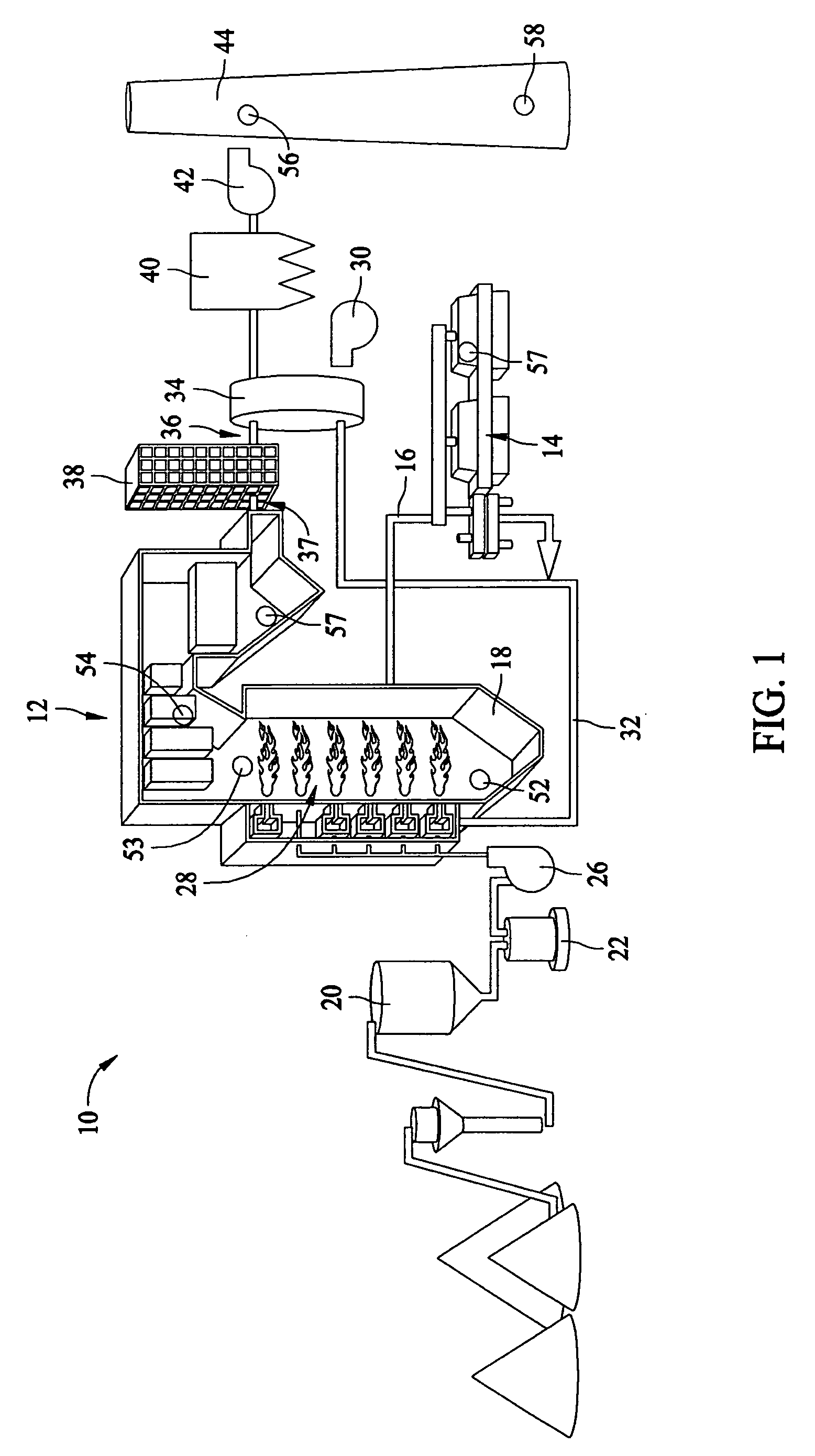
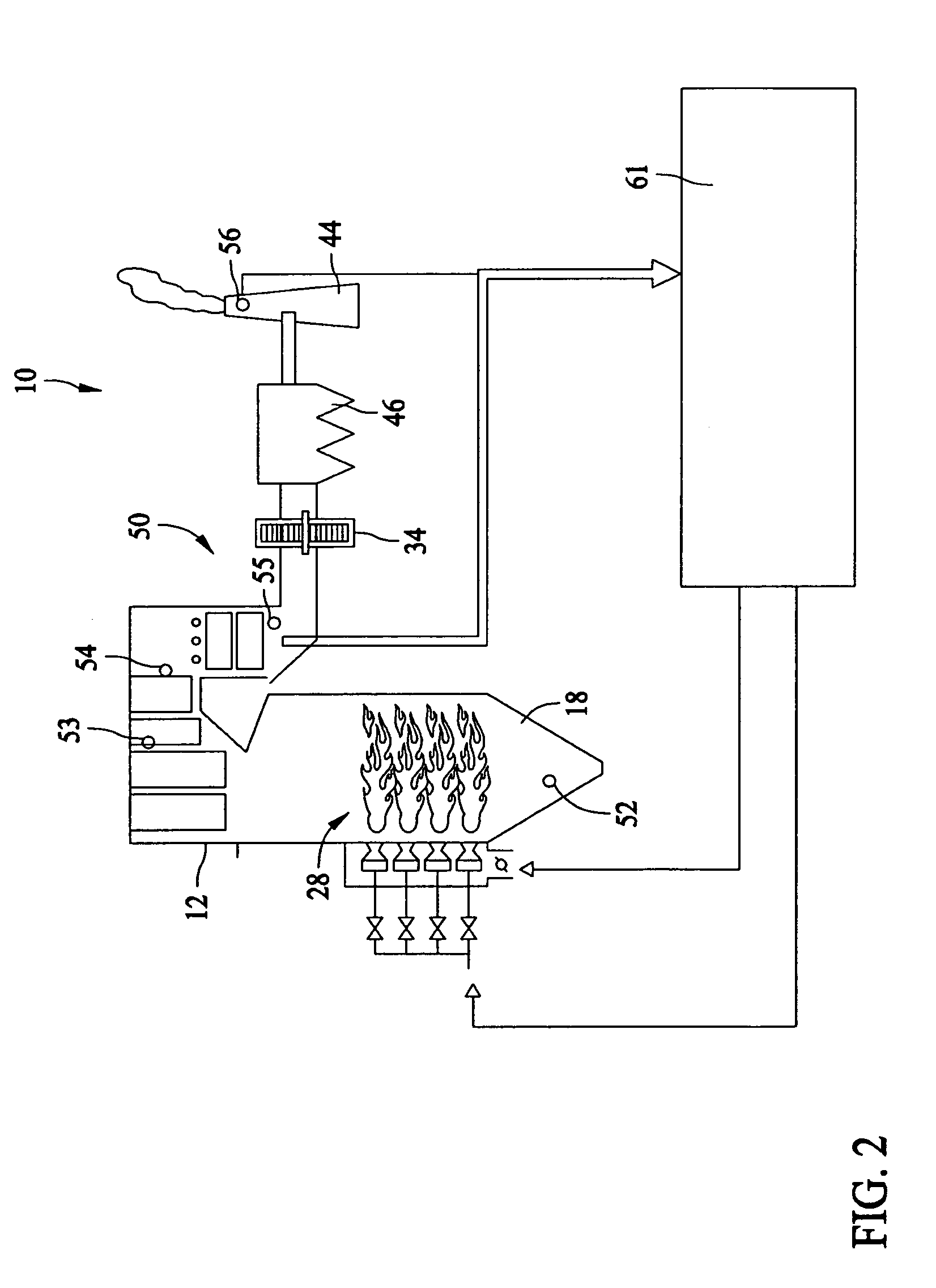
[0022]The present invention provides a sensing method and system for monitoring operating conditions and / parameters of a power generating system, such as, without limitation, a fossil fuel fired boiler, a gas turbine and a steam turbine. As an exemplary embodiment, the invention will be described in the context of a boiler system. The sensing method and system detect the presence of gases and / or the concentration of the gases produced a combustion process within the boiler furnace, as well as other operating conditions and / or parameters including, without limitation, temperature, heat flux and / or pressure. The sensing method and system includes an array of sensing modules each positioned at a spatial location within the power generating system to monitor operating conditions and / or parameters, such as combustion conditions that include emissions, temperature and / or pressure. The sensing method and system also includes using the detected information to make adjustments to boiler syst...


PUM


Abstract

A sensing module positioned about an optical fiber cable having a long axis. The optical fiber includes a core that transmits light through the optical fiber cable. The sensing module includes a first short-period fiber grating positioned about the core. A second short-period fiber grating is positioned about the core and at a distance along the long axis with respect to the first short-period fiber grating. At least one of a long-aperiod fiber grating and a long-period fiber grating is positioned between the first short-period fiber grating and the second short-period fiber grating. A fiber cladding is positioned around the long-period grating and/or the long-aperiod grating of the sensing module. A sensing skin is positioned about the fiber cladding and includes a chemical gas active material.

Description

BACKGROUND OF THE INVENTION[0001]This invention relates generally to power generating systems and, more particularly, to a method and system for emission control and combustion optimization in fossil fuel fired boilers with an array of fiber grating-based sensing modules.[0002]In numerous industrial environments, a hydrocarbon fuel is burned in stationary combustors (e.g., boilers or furnaces) to produce heat to raise the temperature of a fluid, e.g., water. For example, the water is heated to generate steam, and this steam is then used to drive turbine generators that output electrical power. Such industrial combustors typically employ an array of many individual burner elements to combust the fuel. In addition, various means of combustion control, such as overfire air, staging air, reburning systems and selective non-catalytic reduction systems, can be employed to enhance combustion conditions and reduce emissions of oxides of nitrogen (NOx) and carbon monoxide.[0003]Emissions and...

Claims


Application Information

Patent Timeline
Patent Type & Authority Patents(United States)
IPC IPC(8): G02B6/34
CPCG01K11/3206G01N21/774G01N2021/7783G02B6/02104G02B6/29319Y02E50/12Y02E50/10
Inventor XIA, HUADENG, KUNG-LI JUSTINMCCARTHY, KEVIN THOMASTAWARE, AVINASH VINAYAK
Owner GENERAL ELECTRIC CO
Why Eureka
Try Eureka