Oxidation-protected metallic foil and method

a technology of oxidation-protected metallic foil and metal foil, which is applied in the manufacture of electrode systems, discharge tube luminescnet screens, coupling device connections, etc., can solve the problems of lamp failure, substantial reduction in the useful life of lamps, and foil corrosion

Inactive Publication Date: 2006-12-26
ADVANCED LIGHTING TECH
View PDF44 Cites 5 Cited by
  • Summary
  • Abstract
  • Description
  • Claims
  • Application Information

AI Technical Summary

Problems solved by technology

However, molybdenum oxidizes rapidly when exposed to oxygen at temperatures greater than about 350° C. Since the foils in electrical lead assemblies in electric lamps are often exposed to temperatures greater than about 350° C., the metallic foil may be highly susceptible to oxidation resulting in a breach of the electrical path or the gas-tight integrity of the hermetic seal resulting in lamp failure.
Typically, a molybdenum foil exposed to a reactive atmosphere will not oxidize appreciably below about 350° C. At temperatures greater than about 350° C., the rate of the reaction between the oxygen in the surrounding atmosphere and the molybdenum foil greatly increases resulting in corrosion of the foil and a substantial reduction in the useful life of the lamp.
The electrode lead assemblies provide a point of failure in such lamps due to corrosion, e.g., oxidation, of the metallic foils when exposed to corrosive agents such as oxygen at high temperatures.
Eventually, the electrical path may be breached or the pinch seal may crack causing the lamp to fail.
One reason for this failure is that during the formation of a pinch seal or vacuum seal with a vitreous material such as quartz, the quartz does not completely seal to the relatively thicker outer and inner lead wires, due at least in part to the relatively high viscosity of the quartz.
However, these prior art coatings are not desirable because the coatings are relatively thick and do not bond well to glass.
The utility of the prior art coatings is also limited because the coatings cannot be exposed to high operating temperatures.

Method used


Image

  • Oxidation-protected metallic foil and method
  • Oxidation-protected metallic foil and method
  • Oxidation-protected metallic foil and method

Examples


example 1

[0046]Pieces of molybdenum foil were coated with silica glass employing various coating methods. In one application, the ribbon was dipped into a bath of colloidal silica (20% SiO2 in methanol; 300 nm and long chains of 5–20 nm) provided by Nissan Chemical Co. (product no. MA-ST-UP) and pulled into air at a rate of several millimeters per second. The ribbon was then heated to 1600–1650° C. for a period of one second. This caused the small silica particles to be fused into a thin, continuous film of glass which was substantially impervious to oxidation. As the foil cooled, the metallic portion contracted more than the silica coating thereby placing the glassy film under lateral compression. The lateral compression of the film enhances the film's resistance to cracking and other surface damages.

[0047]Similar experiments were conducted in which the heating duration was extended to 4 seconds and it was learned that extended heating can cause brittleness in the foil. It is noted that the...

example 2

[0048]A thin film of silica was applied to a molybdenum foil to form an oxidation-protective film. The foil was dip-coated by immersing the foil in a bath and withdrawing it from the bath at a rate of 1 inch / sec.

[0049]The bath contained:

[0050]

ST-OUP (from Nissan Chemical Corp.)3.0 gmDistilled Water2.0 gmConcentrated aqueous ammonia  3 drops (ca. 0.15 mL)PVP (1% solution in water)3.0 gm

[0051]The ingredients were added in the above-recited order under gentle swirling. The foil was then coated with the solution, air-dried and heated to about 1600° C. for about one second in argon atmosphere.

example 3

[0052]The following procedure was conducted to coat a molybdenum foil with a film of silica. The molybdenum foil was dip-coated by immersing the foil in a bath and withdrawing the foil from the bath at a rate of about 1 inch / sec.

[0053]The bath contained:

[0054]

ST-OUP (from Nissan Chemical Co.)3.0 gmDistilled water2.0 gmConcentrated aqueous ammonia  3 drops (ca. 0.15 mL)PVP (1% solution in water)3.0 gm

[0055]The ingredients were added in the above order under a gentle swirl. A positive electrical potential was applied to the foil during the immersion and withdrawal of the foil from the bath (e.g., 3 volts, relative to a platinum wire immersed in the bath). This process resulted in a reduction of the number of coating irregularities on the thin edges of the foil. After the foil was coated, it was air-dried and then heated to about 1600° C. in argon atmosphere for about 1 second. The foil was found to be covered by a even layer of silica.


PUM

PropertyMeasurementUnit
temperatureaaaaaaaaaa

Abstract

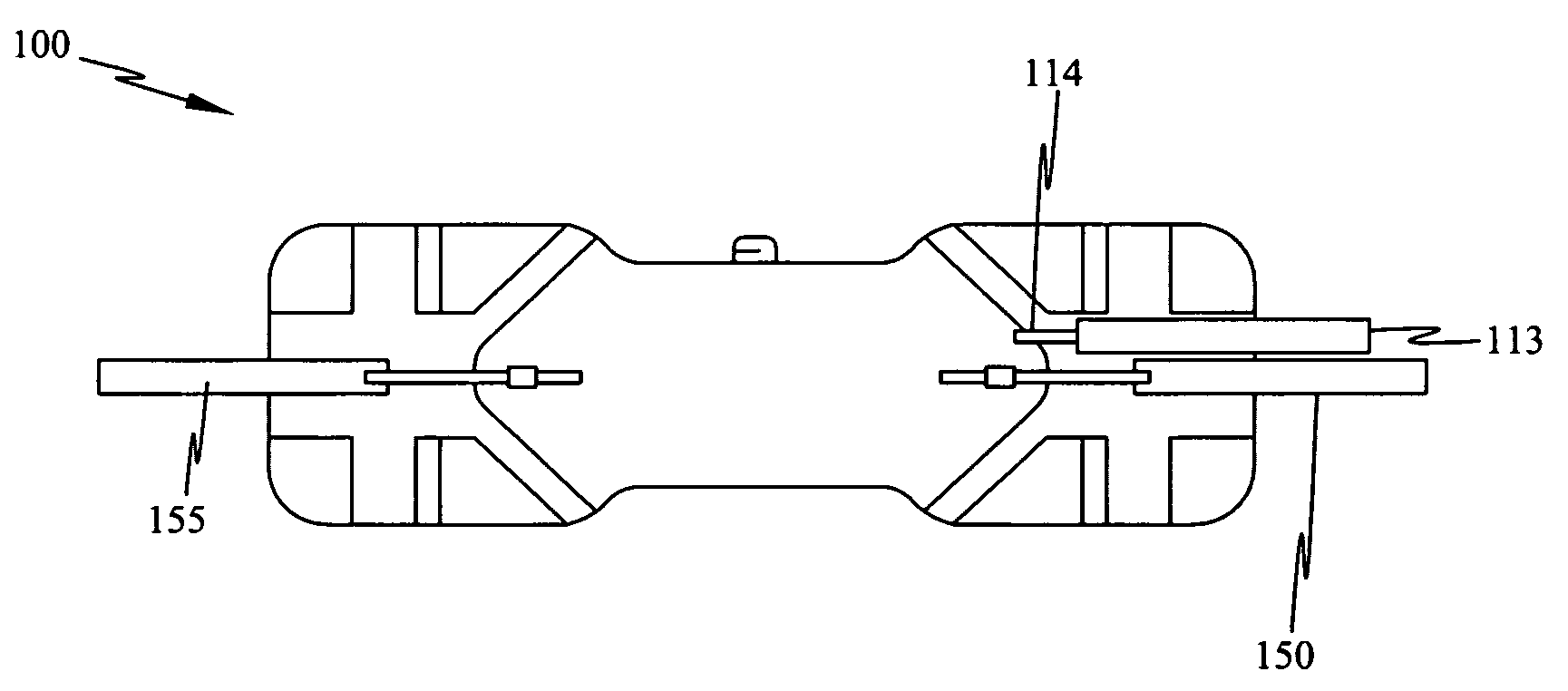
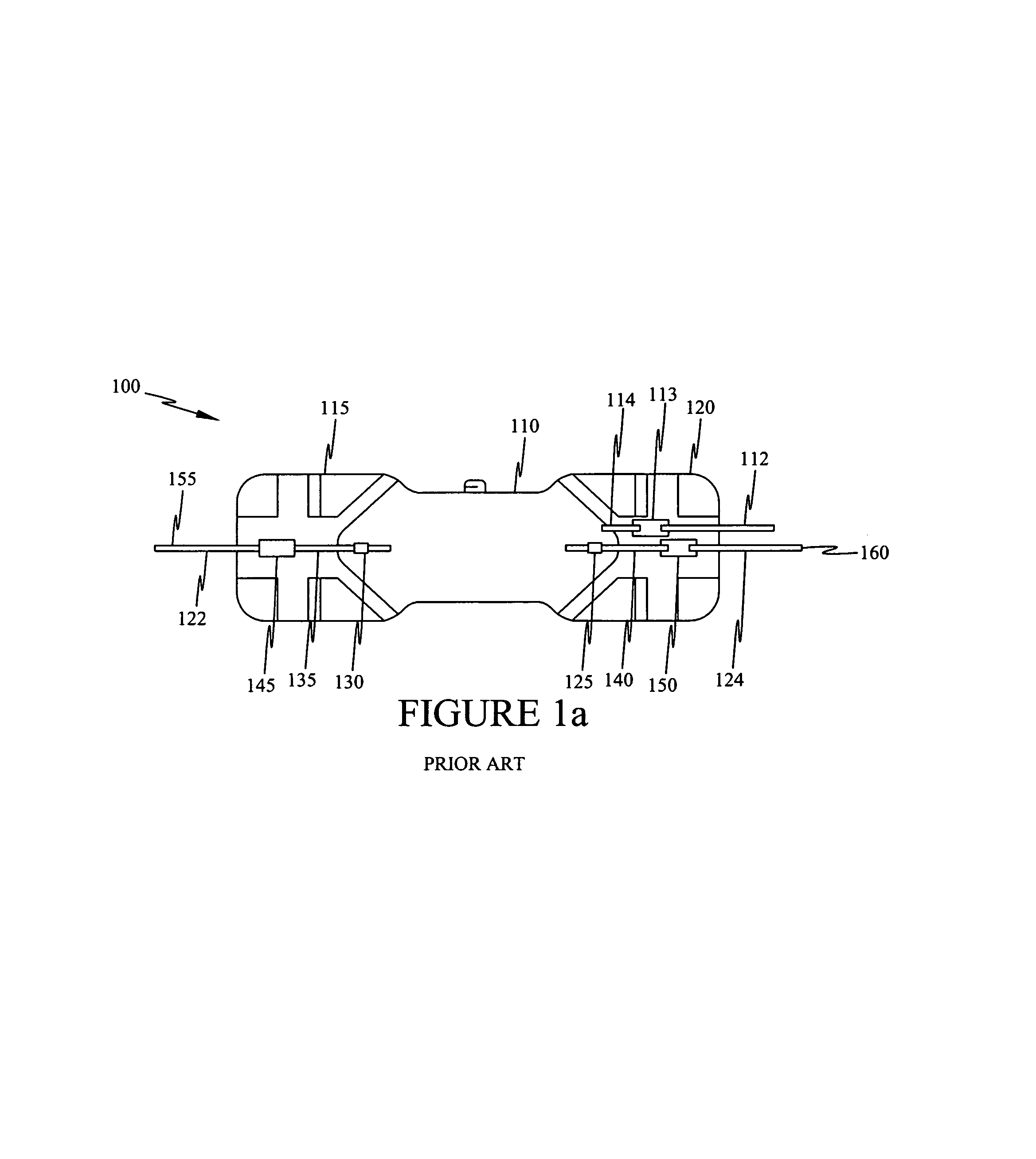
An electrical lead assembly for devices such as electrical lamps having a metallic foil for providing an electrically conducting path through a hermetic seal formed by pinch sealing a vitreous material. The metallic foil includes an oxidation-inhibiting coating of silica. In another aspect of the invention, methods of coating metallic foils with silica are disclosed. In yet another aspect of the present invention, an electrical lead assembly for lamps is provided wherein the metallic foil is extended to form an outer electrical lead for the lamp.

Description

RELATED APPLICATIONS[0001]This application claims the filing-date benefit of U.S. Provisional Patent Application Ser. No. 60 / 424,338 filed Nov. 7, 2002, and incorporates said application herein in its entirety.BACKGROUND OF THE INVENTION[0002]The present invention generally relates to electrical lead assemblies in devices such as electric lamps for providing an electrical path through a hermetic press or pinch seal formed in a vitreous material such as fused silica or hard glass. More specifically, the present invention relates to such assemblies having a metallic foil with an oxidation-protective coating on at least a portion of the foil.[0003]In certain devices, it is often necessary to provide an electrically-conducting path through a pinch or press seal formed in a vitreous material. For example, in devices such as electric lamps, e.g., halogen incandescent filament bulbs and high intensity discharge arc tubes, a light emitting chamber is formed from a vitreous material having o...

Claims


Application Information

Patent Timeline
Patent Type & Authority Patents(United States)
IPC IPC(8): B05D1/04B05D1/12B05D1/18H01J9/00C23C30/00H01J5/46H01J9/28H01J9/32H01J17/04H01J17/18H01J61/36H01K1/40H01K3/20H01RH01R33/965
CPCC23C30/00H01J5/46H01J9/28H01J9/326H01J61/36H01J61/368H01K1/40H01K3/20H01R33/965
Inventor EMILSSON, TRYGGVI
Owner ADVANCED LIGHTING TECH
Why Eureka
Try Eureka