Microfabricated ion trap array

Active Publication Date: 2006-12-26
NAT TECH & ENG SOLUTIONS OF SANDIA LLC
View PDF6 Cites 69 Cited by
  • Summary
  • Abstract
  • Description
  • Claims
  • Application Information

AI Technical Summary

Benefits of technology

[0019]The present invention is directed to a microfabricated ion trap array, comprising an insulating substrate; a bottom endcap electrode layer, comprising a plurality of interconnected bottom endcap electrodes, on the substrate; a center ring electrode layer, comprising a plurality of interconnected ring electrodes axially aligned with the plurality of bottom endcap electrodes and separated therefrom by an air gap; a top endcap electrode layer, comprising a plurality of interconnected top endcap electrodes axially aligned with the plurality of ring electrodes and separated therefrom by an air gap; and means for applying a radiofrequency drive voltage between the center ring electrode layer and the endcap electrode layers to provide an ion trap in each of the intraelectrode volumes formed by the plurality of aligned bottom endcap electrodes, ring electrodes, and top endcap electrodes. Each top endcap electrode can further comprise an injection aperture for injecting an ionized or neutral sample gas into the intraelectrode volume. Each bottom endcap electrode can further comprise an extraction aperture for ejecting ions from the intraelectrode volume. The microfabricated ion trap array can further comprise an ion collector layer between the substrate and the bottom endcap electrode layer, the ion collector layer comprising a plurality of interconnected ion collectors axially aligned with the plurality of bottom endcap electrodes and separated therefrom by an air gap. The substrate can be silicon and the electrodes can be a metal, such as tungsten. The microfabricated ion trap array can have individual trap dimensions of order one micrometer (i.e., generally from about ten microns to sub-micron in radius). Massive arraying enables the microfabricated ion trap array to retain the mass range, resolution, and sensitivity advantages necessary for high chemical selectivity.
[0020]The microscale ion trap array can be fabricated using surface micromachining techniques and materials known to the integrated circuits (IC) manufacturing and microelectromechanical systems (MEMS) industries. Preferably, the ion trap array can be fabricated using a metal damascene process to build up successive layers of the ion trap structure. Metal damascene is an inlaid process in which a trench is formed in a surface layer and a metal overfill is deposited into the trench. A chemical-mechanical-polishing (CMP) step is used to re-planarize the surface and isolate the metal in the trench. With CMP, the thickness of the layer can be precisely adjusted to provide precise vertical dimensioning of the layers. Such methods enable batch fabrication, reduced manufacturing costs, dimensional and positional precision, and monolithic integration of massive arrays of ion traps with microscale ion generation and detection devices.

Problems solved by technology

Such a device consumes some 2400 W power, with about 40% being required for the rf electrical system and the balance for the vacuum system.

Method used


Image

  • Microfabricated ion trap array
  • Microfabricated ion trap array
  • Microfabricated ion trap array

Examples


Embodiment Construction

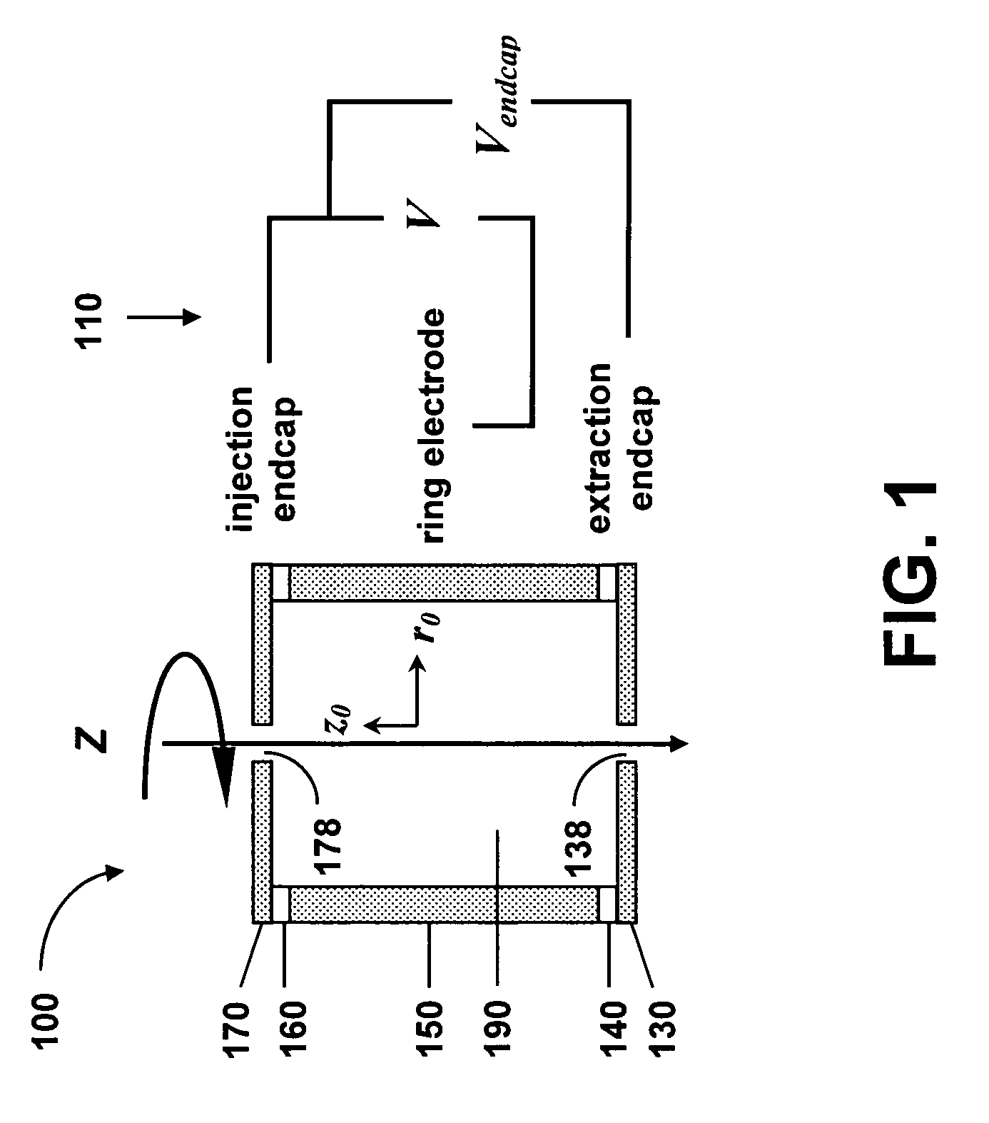
[0040]In FIG. 1 is shown a schematic illustration of a single CIT 100 comprising a cylindrical ring electrode 150, two planar endcap electrodes 130 and 170, and endcap dielectric spacers 140 and 160 between the center ring electrode 110 and the endcap electrodes 130 and 170. Ions are trapped in the intraelectrode trapping volume 190 defined by the cylindrical ring electrode 150 and the endcap electrodes 130 and 170. Apertures 178 and 138 can be provided in the endcap electrodes 170 and 130 for injection of a neutral or ionized sample gas into and ejection of the ions out of the trapping volume 190. The CIT 100 is rotationally symmetric about the axial Z axis. r0 is the inner radius of the ring electrode 150 and z0 is the center-to-endcap distance. The CIT 100 can be energized by a power source 110 that provides a rf drive voltage V between the ring electrode 150 and the endcap electrodes and a dc or rf voltage Vendcap between the two endcap electrodes 170 and 130 for trapping of the...


PUM


Abstract

A microfabricated ion trap array, comprising a plurality of ion traps having an inner radius of order one micron, can be fabricated using surface micromachining techniques and materials known to the integrated circuits manufacturing and microelectromechanical systems industries. Micromachining methods enable batch fabrication, reduced manufacturing costs, dimensional and positional precision, and monolithic integration of massive arrays of ion traps with microscale ion generation and detection devices. Massive arraying enables the microscale ion traps to retain the resolution, sensitivity, and mass range advantages necessary for high chemical selectivity. The reduced electrode voltage enables integration of the microfabricated ion trap array with on-chip circuit-based rf operation and detection electronics (i.e., cell phone electronics). Therefore, the full performance advantages of the microfabricated ion trap array can be realized in truly field portable, handheld microanalysis systems.

Description

CROSS-REFERENCE TO RELATED APPLICATION[0001]This application claims the benefit of U.S. Provisional Application No. 60 / 610,395, filed Sep. 16, 2004, which is incorporated herein by reference.STATEMENT OF GOVERNMENT INTEREST[0002]This invention was made with Government support under contract no. DE-AC04-94AL85000 awarded by the U.S. Department of Energy to Sandia Corporation. The Government has certain rights in the invention.FIELD OF THE INVENTION[0003]The present invention relates to ion storage and analysis and, in particular, to a microscale ion trap array fabricated using surface micromachining techniques.BACKGROUND OF THE INVENTION[0004]A mass spectrometer (MS) is a device that filters gaseous ions according to their mass-to-charge (m / z) ratio and measures the relative abundance of each ionic species. Mass spectrometry is particularly attractive for in-situ analysis, due to its inherent speed, excellent sensitivity, molecular selectivity, and capability for continuous real-time...

Claims


Application Information

Patent Timeline
IPC IPC(8): H01J49/42
CPCH01J49/0018H01J49/424
Inventor BLAIN, MATTHEW G.FLEMING, JAMES G.
Owner NAT TECH & ENG SOLUTIONS OF SANDIA LLC
Why Eureka
Try Eureka