Back light assembly, liquid crystal display apparatus and manufacturing method thereof

a liquid crystal display and back light technology, applied in mechanical devices, lighting and heating devices, instruments, etc., can solve the problems of increasing manufacturing costs, consuming more power, and affecting the brightness of the area, so as to reduce thickness, remove bright lines and waterfall, and high brightness

Inactive Publication Date: 2006-12-26
SAMSUNG DISPLAY CO LTD
View PDF10 Cites 27 Cited by
  • Summary
  • Abstract
  • Description
  • Claims
  • Application Information

AI Technical Summary

Benefits of technology

[0023]Accordingly, it is an aspect of the present invention to provide to a liquid crystal display apparatus having advantages th

Problems solved by technology

Firstly, as illustrated in FIG. 2, the conventional direct-down type liquid crystal display apparatus 100 has the disadvantage that bright lines occur on an area “a” on the direct front of the lamp 121 becomes brighter than an area “b” on the front of a space positioned between the lamps 121.
Secondly, to prevent the bright lines caused by difference of the brightness of each lamp 121, a distance “Q” between the lamp 121 and the optical sheet layer 123 has to be increased, which makes the flattening of the liquid crystal display apparatus 100 hard. Also, in case that a distance “P” between the lamps 121 is decreased, it may prevent occurrence of the bright lines on the liquid crystal display panel 110, however it has disadvantages that it increases a manufacturing cost and consumes more power.
Thirdly, in the conventional direct-down type liquid crystal display apparatus 100, the lamp 121 on the rear of the optical sheet layer 123 radiates heat as well as it emits the light. The heat radiated from the lamp 121 deteriorates the liquid crystal display panel 110 and the optical sheet layer 123 and, as a result, it decreases the brightness of the liquid crystal display apparatus 100 due to the heat. FIG. 3 illustrates variation of the brightness according to passage of time during an operation of the conventional direct-down type liquid crystal display apparatus 100. Here, “A” in FIG. 3 represent

Method used


Image

  • Back light assembly, liquid crystal display apparatus and manufacturing method thereof
  • Back light assembly, liquid crystal display apparatus and manufacturing method thereof
  • Back light assembly, liquid crystal display apparatus and manufacturing method thereof

Examples


first embodiment

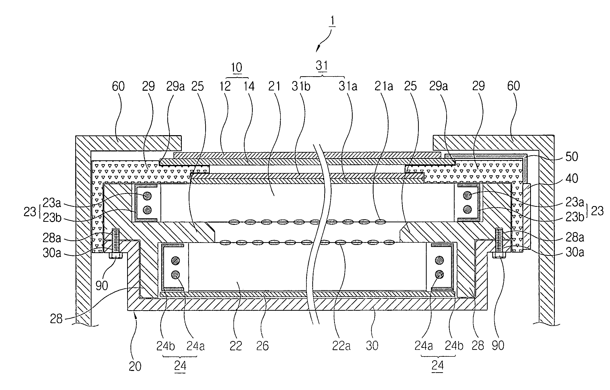
[0054]As illustrated in FIG. 4, a liquid crystal display apparatus 1 according to the present invention comprises a liquid crystal display panel 10 displaying a picture, a back light assembly 20 provided on a rear of the liquid crystal display panel 10 and emitting light onto the liquid crystal display panel 10, a PCB (printed circuit board) 40 to apply a visual signal to the liquid crystal display panel 10, and a front chassis 60 covering front circumference of the liquid crystal display panel 10.

[0055]The liquid crystal display panel 10 comprises a first panel 14 formed with a switching component like a TFT (thin film transistor) and with a pixel electrode, a second panel 12, and a liquid crystal (not shown) inserted between the first panel 14 and the second panel 12. Herein, the visual signal applied by the PCB 40 is transferred to a thin film transistor on the first panel 14 via a drive IC (not shown). Accordingly, the liquid crystal applied with an electric signal displays a pi...

second embodiment

[0073]Hereinbelow, an assembly process of the liquid crystal display apparatus 1′ according to the present invention, for example, will be described in reference to FIGS. 7 through 10.

[0074]Firstly, as illustrated in FIG. 7, the mold frame 28 is provided on a predetermined working table in a way that the rear accommodation space of the mold frame 28 integrated with the spacing part 25′ faces upward. The second light guide plate 22 is place on the spacing part 25′ to accommodate the second light guide plate 22 in the rear accommodation space of the mold frame 28, and then the reflector panel 26 is installed on the second light guide plate 22.

[0075]Upon completing the process described above, as illustrated in FIG. 8, the rear frame 30 covers the rear accommodation space of the mold frame 28 as the second light guide plate 22 and the reflector panel 26 is accommodated in the rear accommodation space. Herein, the rear frame 30 may be combined to the mold frame 28 by the screw 90 as des...


PUM


Abstract

A iquid crystal display apparatus that comprises: a liquid crystal display panel that displays a picture; a plurality of light guide plates that are installed on a rear of the liquid crystal display panel and are spaced from each other; and a back light assembly with a lamp assembly that emits light toward each light guide plate. As described above, the present invention provides the back light assembly and the liquid crystal display apparatus improving the brightness, reducing the thickness, removing the bright lines and the waterfall on the liquid crystal display panel, and lowering the manufacturing cost.

Description

CROSS-REFERENCE TO RELATED APPLICATIONS[0001]This application claims the benefit of Korean Patent Applications No. 2003-0034921, filed May 30, 2003, and No. 2002-0059207, filed Sep. 28, 2002, in the Korean Intellectual Property Office, the disclosure of which are incorporated herein by reference.BACKGROUND OF THE INVENTION[0002]1. Field of the Invention[0003]The present invention relates to a liquid crystal display apparatus, further particularly to a liquid crystal display apparatus having advantages that it provides high brightness, a reduced thickness, while removing bright lines and waterfall and lowering a manufacturing cost.[0004]2. Description of the Related Art[0005]A liquid crystal display is a display device using a liquid crystal cell for modification of light, or a device turning variation of optical property such as birefringence, circumpolarization, dichroism, and light scattering caused by rearrangement of liquid crystal particles into visual variation by applying vol...

Claims


Application Information

Patent Timeline
IPC IPC(8): G02F1/1333G02F1/1335G02B6/00F21V8/00F21Y103/00G02F1/13357G02F1/1345
CPCG02B6/0043G02B6/0076G02B6/0088G02F1/133615G02F1/133611G02F2001/133317G02F1/133608G02F1/133317
Inventor LEE, HEA-CHUN
Owner SAMSUNG DISPLAY CO LTD
Why Eureka
Try Eureka