Eureka AIR delivers breakthrough ideas for toughest innovation challenges, trusted by R&D personnel around the world.

Broadband Raman amplifier

Inactive Publication Date: 2006-12-26
RPX CORP
View PDF21 Cites 0 Cited by
  • Summary
  • Abstract
  • Description
  • Claims
  • Application Information

AI Technical Summary

Benefits of technology

[0008]The present invention aims to provide a pump laser for Ramon amplification which mitigates some or all of these problems.
[0011]Thus by producing multiple wavelength pump radiation from a single pump source, the number of pump sources which need to be provided can be reduced. Preferably only one pump source is included although in some circumstances more than one pump source may be provided with each pump source producing a plurality of different wavelengths of pump radiation. Also further pump source(s) may need to be provided for the purposes of redundancy.
[0015]In some embodiments, rather than providing continuously variable levels of attenuation (or even a plurality of separate discrete levels of attenuation), each variable attenuator may only provide one level of attenuation. That is to say, for example, each variable optical variable attenuator may in fact be an optical switch providing either substantially no attenuation or substantially 100% attenuation depending on the setting of the switch. In such embodiments, the switches may be set so that only some, or indeed only one, of the reflectors provides optical feedback to the pump at any one time. In this way it is possible to provide a discretely wavelength tuneable amplifier spectrum using fewer (and preferably only one) pump source. Again, control means may be provided for selectively controlling the switches in order to change the overall characteristics of the amplifier.
[0017]Alternatively, instead of having to temperature stabilise the pump source, variations in the output power of the laser with temperature could be compensated by controlling the input current supplied to the laser. This is particularly suitable with the second embodiment described above utilising the optical switches.

Problems solved by technology

However this solution has a number of drawbacks mainly resulting from the fact that more than one pump source is required.
Firstly, pumps are expensive components and secondly the inclusion of a number of pumps will substantially increase the size of the amplifiers.
Also the use of a number of pumps will increase the pump driving current requirements, which can be particularly restrictive where the amplifier is for use in submarine fibre optical cable systems where the line current has to be kept reasonably low.
Furthermore, in systems where higher reliability is needed, the number of redundant pumps included may be as high as the number of working pumps which in turn exaggerates the problems of cost, size and complexity for the amplifier.

Method used


Image

  • Broadband Raman amplifier
  • Broadband Raman amplifier
  • Broadband Raman amplifier

Examples


Embodiment Construction

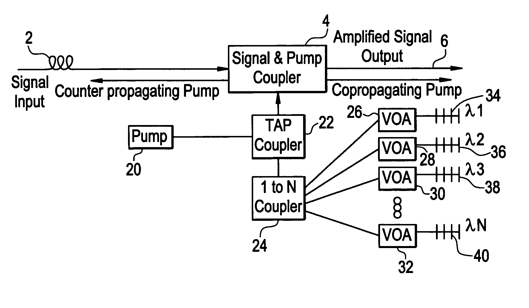
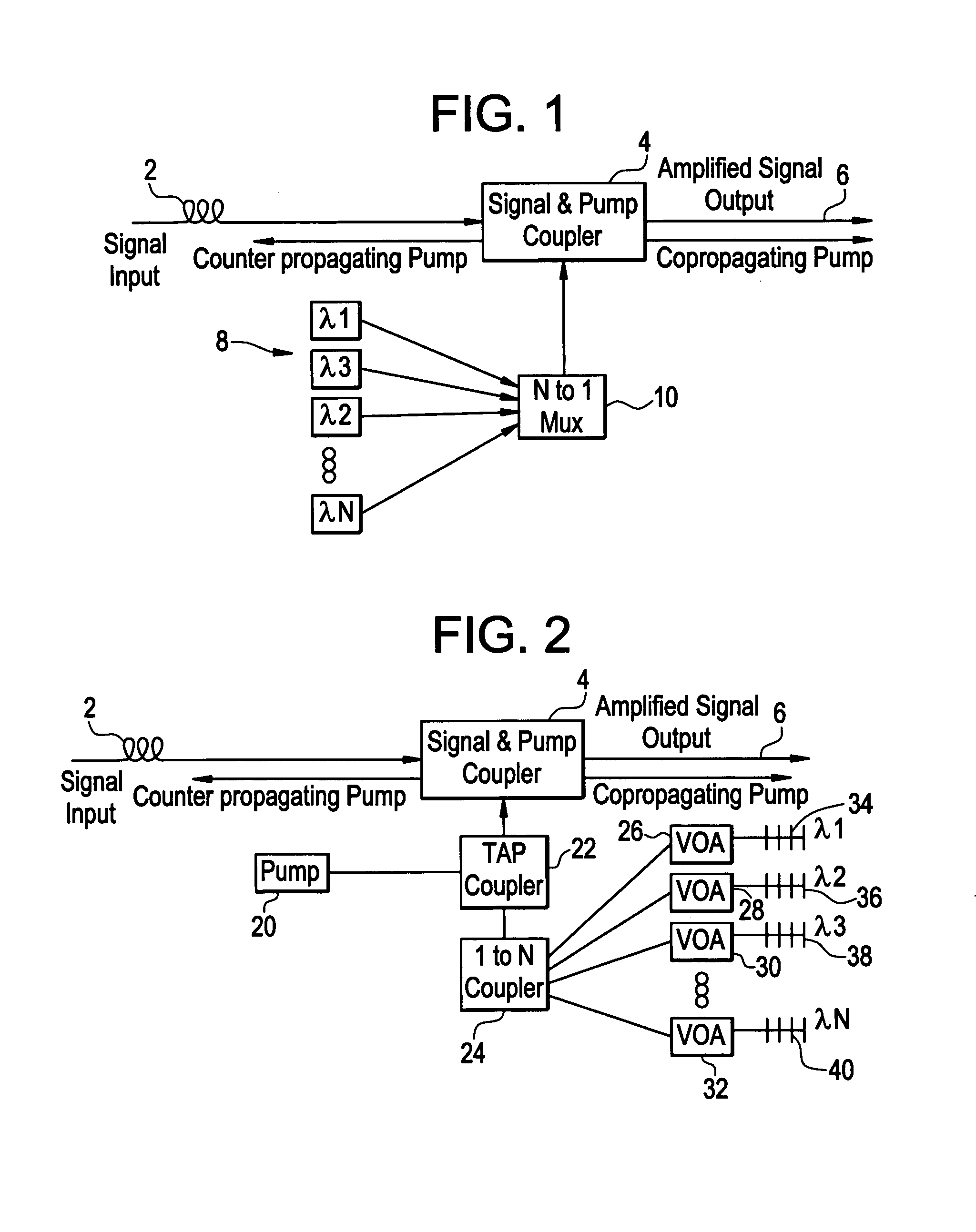
[0024]In FIG. 2, a signal to be amplified is input along transmission fibre 2. Pump radiation is provided to fibre 2 via the signal and pump coupler 4. Raman amplification is taking place in fibre 2 and the amplified signal is output on a fibre 6. A single pump 20 is provided which preferably produces pump radiation of substantially wide bandwidth. The pump radiation is fed to a TAP coupler 22 which in turn feeds the pump radiation to a further coupler 24.

[0025]The coupler 24 couples the pump radiation to a plurality of variable optical attenuators. In FIG. 2 only four optical attenuators 26, 28, 30, 32 are illustrated but of course any number may be included. Each of the optical attenuators 26–32 is associated with a respective reflector 34–40. The reflectors can, for example, be fibre Bragg gratings. Each grating 34–40 produces reflected radiation of correspondingly different wavelengths, which is shown in FIG. 2 as λ1, λ2, λ3 and λN (indicating the possibility for N pump waveleng...


PUM


Abstract

The present invention provides a wide bandwidth, gain flattened Raman amplifier including a laser source of pump radiation, and means for producing from the pump source a plurality of wavelengths of pump radiation including means for providing adjustable optical feedback to the pump source at a plurality of radiation wavelengths. Alternatively, instead of or in addition to the means for providing adjustable optical feedback, the invention may include means for independent power control of each wavelength.The amplifier may include a coupler for coupling the pump radiation into the signal fiber and may include the fiber (which can be the transmission fiber) where the amplification takes place.

Description

BACKGROUND OF THE INVENTION[0001]The present invention relates to optical amplifiers and in particular to wide bandwidth optical amplifiers. The present invention is particularly applicable to Raman amplifiers.[0002]Raman amplification is considered to be particularly suitable for use in wideband and ultra wideband optical amplifiers, for example used in wavelength division multiplexing transmission systems. The reason for this is that, unlike Erbium doped fibre amplifiers, gain can be provided at a predetermined range of wavelengths by choosing a suitable pump wavelength. In addition, Raman amplification can be distributed along a transmission fibre, giving an improved optical signal-to-noise ratio, lower signal launch power and therefore longer transmission distances without requiring further amplification and / or repetition.[0003]However one drawback is that for a Raman amplifier using a single pump wavelength only, the gain profile of the amplifier is far from flat. Typically the...

Claims


Application Information

Patent Timeline
IPC IPC(8): H01S3/00G02F1/35H01S3/06H01S3/10H01S3/30H04B10/291
CPCH04B10/2916H01S3/302
Inventor ZARRIS, GEORGERODRIGUEZ LLORENTE, FERNANDO
Owner RPX CORP
Why Eureka
Eureka Blog
Learn More