Plasma CVD apparatus

a cvd and plasma technology, applied in glass making apparatus, manufacturing tools, electric/magnetic/electromagnetic heating, etc., can solve the problems of increasing the increase of the propagation loss of the microwave, and the increase of the loss of the waveguide, so as to prevent the overheating of the annular waveguide and the lowering of the radiation efficiency of the microwave

Inactive Publication Date: 2007-01-02
KOBE STEEL LTD
View PDF20 Cites 6 Cited by
  • Summary
  • Abstract
  • Description
  • Claims
  • Application Information

AI Technical Summary

Benefits of technology

[0045]According to the present invention, since the cooler is disposed between the annular waveguide and the reaction chamber, it is possible to prevent overheating of the annular waveguide. Besid

Problems solved by technology

In the prior art 1, the annular waveguide has a water cooling structure, but the cooling portion is the side wall portion of the annular waveguide and the inner periphery surface side opposed to the high temperature quartz tube is not cooled, so that a temperature rise on the inner surface side is unavoidable.
As the temperature of the waveguide becomes high, the surface resistance increases and hence the propagation loss of the microwave increases.
Further, if the influence of surface oxidation based on temperature is also taken into account, the loss by the waveguide becomes large to an unignorable extent.
When the loss by the waveguide becomes large, not only the microwave supply efficiency is deteriorated in proportion to the loss, but also the waveguide itself b

Method used


Image

  • Plasma CVD apparatus
  • Plasma CVD apparatus
  • Plasma CVD apparatus

Examples


Embodiment Construction

[0061]Embodiments of the present invention will be described hereinunder with reference to the accompanying drawings.

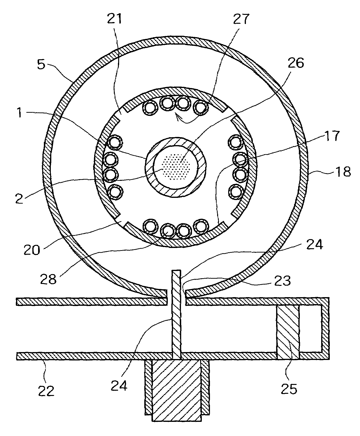
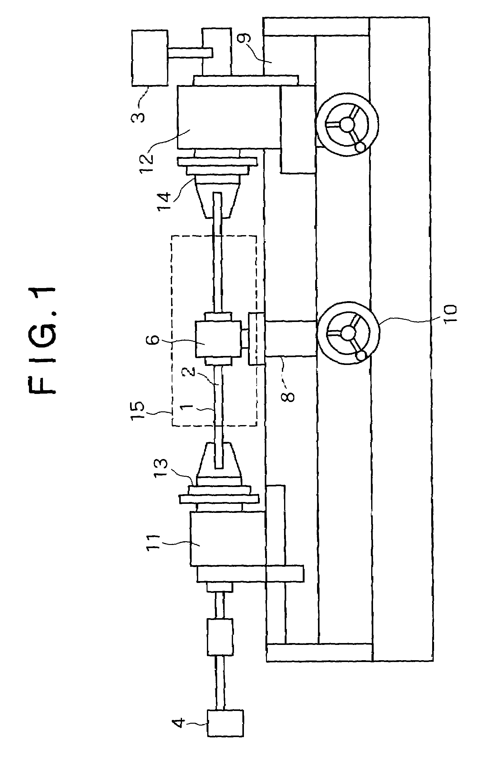
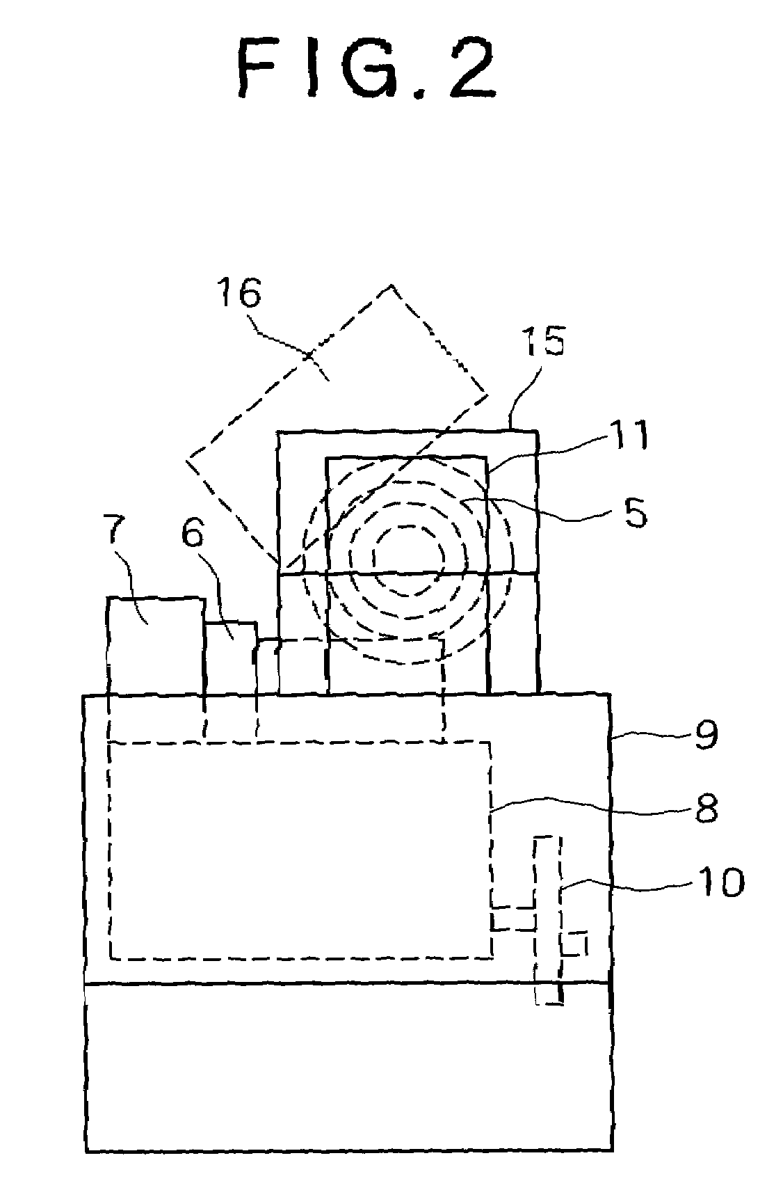
[0062]A plasma-activated CVD system shown in FIGS. 1 and 2 is for producing an optical fiber, in which a silica-based material for example is deposited on an inner surface of a quartz tube 1 to form a film.

[0063]The plasma-activated CVD system is provided with a pressure reducing means 3 for reducing the pressure of a hollow portion 2 of the quartz tube 1, a gas supply means 4 for the supply of gas to the hollow portion 2, and an annular waveguide 5 which radiates a microwave from an outer periphery side of the quartz tube 1 to generate plasma of the gas present within the hollow portion 2, thereby forming a film on an inner surface of the hollow portion 2.

[0064]In this embodiment, the hollow portion 2 of the quartz tube 1 is used as a reaction chamber and the quartz tube 1 itself is used as a substrate tube, with a film being formed on an inner surface of the substra...


PUM

PropertyMeasurementUnit
Angleaaaaaaaaaa
Angleaaaaaaaaaa
Melting pointaaaaaaaaaa

Abstract

A plasma CVD apparatus in which microwave power is supplied into a reaction chamber provided inside an annular waveguide through an antenna provided on the inner peripheral part of the waveguide to produce a plasma inside the reaction chamber and to form a film by a vapor growth synthesizing method. A cooler is disposed between the annular waveguide and the reaction chamber to maintain the low temperature of the annular waveguide.

Description

FIELD OF ART[0001]The present invention relates to a plasma-activated CVD system.BACKGROUND ART[0002]The following conventional methods are known as a plasma-activated CVD (chemical vapor deposition) method wherein a gaseous mixture is fed into a reaction chamber disposed inside an annular waveguide, a microwave power is fed from an antenna installed in an inner periphery portion of the waveguide, causing plasma to be generated within the reaction chamber, and a film is formed by a vapor growth synthesis method.Prior Art 1[0003]There has been known a method wherein, as a material of optical fiber having a core layer and a clad layer different in refractive index, a film is formed on an inner surface of a cylindrical quartz tube by a plasma-activated CVD method. As a plasma-activated CVD system for forming such a material there is known one which is described on pages 66˜72 of “International Wire & Cable Symposium Proceeding 1998.”[0004]According to this known art, a substrate tube i...

Claims


Application Information

Patent Timeline
IPC IPC(8): C23C16/00C23F1/00H01J7/24H01L21/306H05B31/26B01J19/08C03B37/018C23C16/511H01J37/32H05B6/70H05B6/80H05H1/24H05H1/46
CPCC03B37/0183C03B37/01884C23C16/511H05H1/46H01J37/32522H05B6/701H05H1/24H01J37/32192H05H1/4622H05H1/463H05H1/18
Inventor TAMAGAKI, HIROSHIOKIMOTO, TADAOYUTAKA, HIDEKI
Owner KOBE STEEL LTD
Why Eureka
Try Eureka