Method for inserting weft yarns

a technology of weft yarn and insertion method, which is applied in the directions of knitting, weaving, transportation and packaging, etc., can solve the problems of long insertion time dictated by this method, the very high efficiency potential of modern weaving machines cannot be used satisfactorily, and the mechanical load of the weft yarn is high, so as to reduce the tension or attenuate the rise of the yarn tension. , the effect of good yarn control

Inactive Publication Date: 2007-01-02
IROPA AG (CH)
View PDF9 Cites 11 Cited by
  • Summary
  • Abstract
  • Description
  • Claims
  • Application Information

AI Technical Summary

Benefits of technology

[0045]According to a further alternative an auxiliary support is associated to the front side of the support. The auxiliary support is used to first form a yarn winding package supported from the inner side. Thereafter, the auxiliary support is coaxially pulled away from the support in order to release the yarn winding package section which is intended to be inserted. In this case the pull-back of the auxiliary support can be assisted by a stripper member which may be of advantage to keep the released yarn winding package section in compact shape.
[0046]The stretching effect or whiplash effect at the end of an insertion into a jet weaving machine fed by weft yarns originating from a measuring feeding device is a mechanical consequence of the abrupt deceleration of the inserted weft yarn at the stop element. In order to avoid damages, in practice controlled yarn brakes are employed which start to brake in advance before the weft yarn is caught at the stop element and which gradually decelerate the weft yarn. Controlled yarn brakes of this kind need a precise electronic control system and are complicated and costly. According to an important aspect of the invention the stop element itself which is responsible for the whiplash effect or the stretching effect when reaching the stop position, is used for dampening or attenuating the yarn tension rise at the end of an insertion. That is, the attenuation is carried out in the weft yarn exactly at the location where the undesirable yarn tension rise would come from. For that purpose the stop element can be deflected counter to a predetermined elastic force and over a dampening stroke substantially in circumferential direction of the support. In more detail, the stop element is adjusted from a first catching position in which it starts to dece...

Problems solved by technology

On the other hand this means a high mechanical load for the weft yarn.
The most important drawback is the long insertion time dictated by this method, i.e. the time period between the start of the insertion and the arrival of the then stopped weft yarn at the opposite fabric edge.
The basically very high efficiency potential of modern weaving machines cannot be used satisfactorily due to the long insertion time of such known insertion methods.
The method needs high efforts in terms of the devices but is too slow for modern weaving machines because of the mass inertia of the mechanical elements and a plurality of very precisely controlled movements of the mechanical elements.
In this case an undesirably large space is needed and the achievable insertion speeds are limited.
The random configuration of the weft yarn section easily might lead to disturbances due to weft yarn breakages and yarn tension variations during the withdrawal.
In case that then the stop element would be moved from the engaging stop position into no longer engaging the release position, the tension depending friction of the weft yarn at the moving stop element could disturb the tubular configuration of the yarn winding package.
Furthermore, the unavoidably occurring relaxation of the tensioned yarn during the m...

Method used


Image

  • Method for inserting weft yarns
  • Method for inserting weft yarns
  • Method for inserting weft yarns

Examples


Embodiment Construction

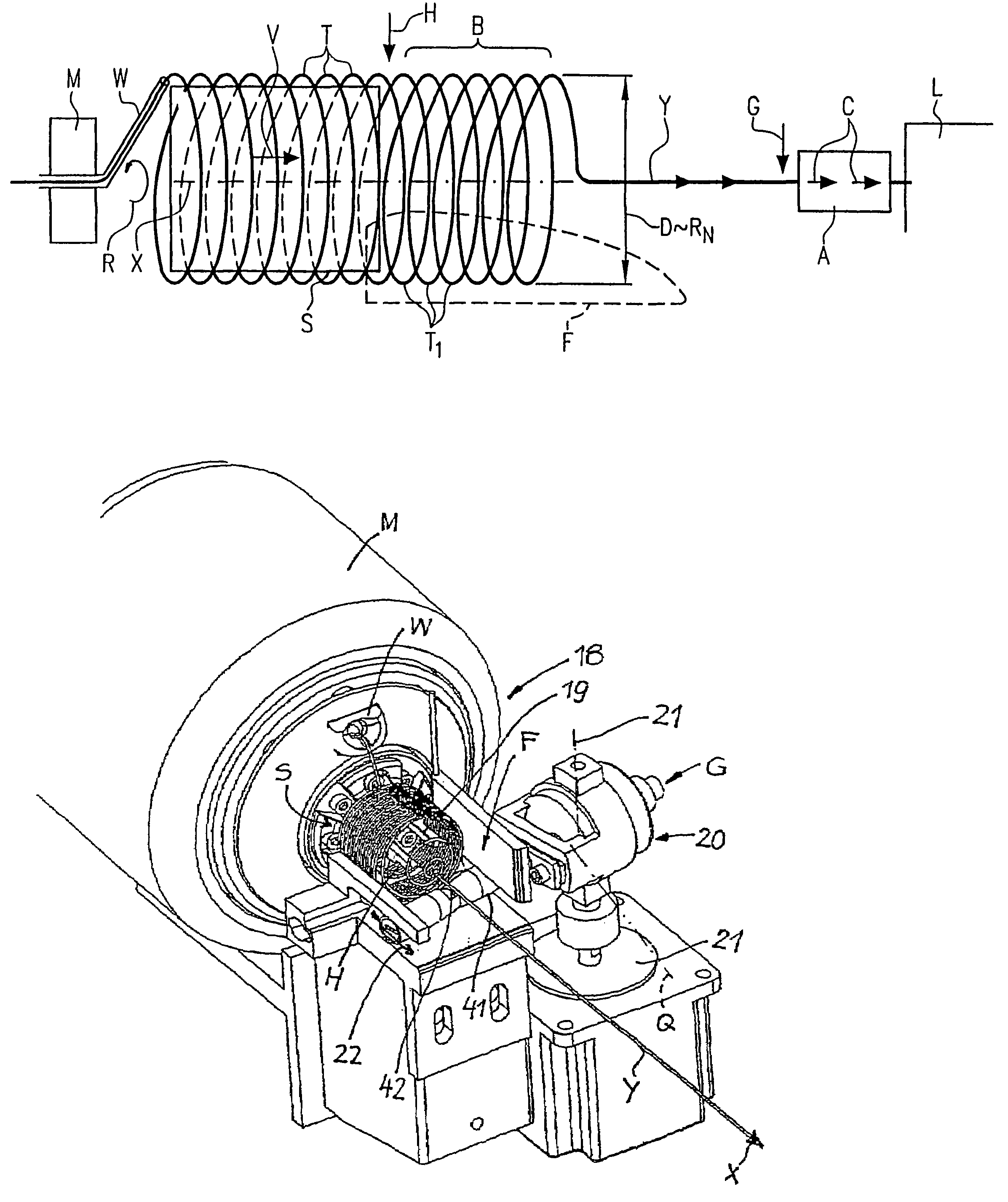
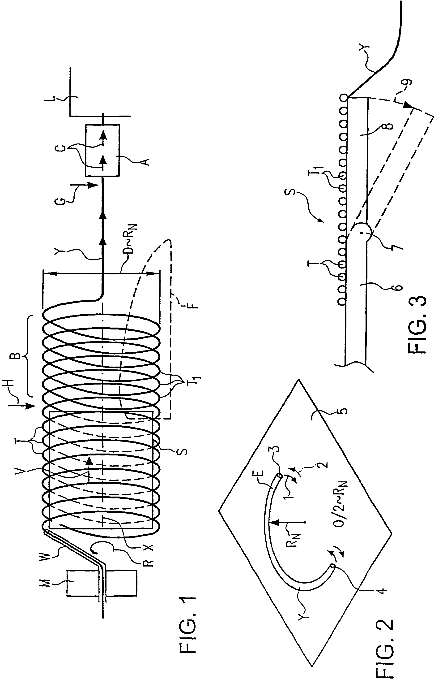
[0072]In FIG. 1 endless weft yarn material Y, e.g. coming from a not shown yarn supply, is pulled into a rotating winding element W which is moved by a drive M with a substantially continuous rotational winding movement R. The weft yarn material Y is wound by the winding element W on an inner mechanical support S in subsequent or adjacently placed windings T as a tubular winding package which moves forward on the support S by a speed V in the direction of an arrow. The windings T then are set free in a winding package section B beyond the end of the support S in withdrawal direction and further in the direction of the axis X from the support S, while they maintain the tubular configuration. In the set free winding package section B the windings T1 are conveyed forward loosely and substantially without tension. Due to inertia and the form stability of the winding package the windings T1 remain free in the space. Approximately in alignment with the axis X an insertion system A of a we...


PUM

PropertyMeasurementUnit
Lengthaaaaaaaaaa

Abstract

The invention relates to a method for inserting weft yarn material, comprising an insertion system in a loom. According to the invention, for every insertion the insertion system (A) is supplied with a substantial part of the weft yarn required for the insertion in a loose and substantially tension-free manner so as to be intermittently pulled off. A tubular package of adjacent windings is produced from the weft yarn material on an inner mechanical support (S) by way of an at least substantially continuous winding process and is conveyed forward in withdrawal direction. For an insertion, a number of windings that corresponds at least approximately to the weft yarn section intended to be inserted is detached or set free from the support while maintaining its tubular configuration without yarn tension. The weft yarn material is withdrawn directly inwardly from the frontmost winding and then further along the tube axis (X).

Description

FIELD OF THE INVENTION[0001]The invention relates to a a yarn feeding device for a weaving machine, and to a method of inserting weft yarns into a weaving machine.BACKGROUND OF THE INVENTION[0002]According to known methods a winding package consisting of contacting or separated and spaced apart windings is formed on a storage body. The insertion system pulls the yarn from the winding package over the front end of the storage body. The windings on the storage body may be advanced forward by different advance assemblies. The storage body is axially longer than the winding package. During withdrawal a yarn balloon is formed which generates significant yarn tension variations and a considerable yarn tension which both delay the insertion. In order to achieve high insertion speeds a considerable energy input thus is needed in the insertion system. On the other hand this means a high mechanical load for the weft yarn. The most important drawback is the long insertion time dictated by this...

Claims


Application Information

Patent Timeline
IPC IPC(8): B65H51/22D03D47/34B65H63/08D03D47/28D03D47/36
CPCB65H63/088D03D47/367D03D47/34B65H2701/31
Inventor HALVARSSON, BJORNMAGNUSSON, PATRIKSVANSTROM, ANDERS
Owner IROPA AG (CH)
Why Eureka
Try Eureka