Fuel cell-use humidifier

a fuel cell and humidifier technology, applied in lighting and heating apparatus, heating types, separation processes, etc., can solve the problems of increased pressure loss, limited use of hollow fiber water-permeable membrane humidifiers, and abrupt decrease in outpu

Active Publication Date: 2007-01-02
UBE IND LTD
View PDF14 Cites 38 Cited by
  • Summary
  • Abstract
  • Description
  • Claims
  • Application Information

AI Technical Summary

Problems solved by technology

Such solid polymer functions, in the hydrous state, as a proton conductive electrolyte but in the dry state, the proton conductivity decreases and at the same time, contact failure occurs between the solid polymer electrolyte membrane and the electrode to cause an abrupt-decrease in the output.
This is proposed to solve the problem that scale-up made to increase the humidification amount leads to increase of the pressure loss even in a low-pressure operation and therefore, use of a hollow fiber water-permeable membrane-type humidifying apparatus is limited.
However, in U.S. Pat. No. 6,464,755, the parameters useful in applying the hollow fiber gas separation membranes to a humidifier for fuel cells are not specifically studied and disclosed.

Method used


Image

  • Fuel cell-use humidifier
  • Fuel cell-use humidifier
  • Fuel cell-use humidifier

Examples


example 1

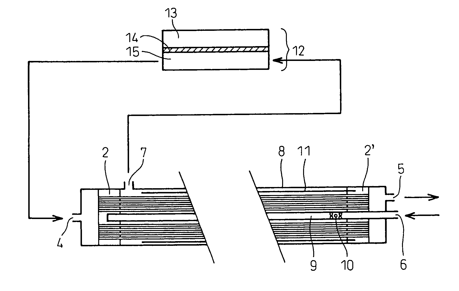
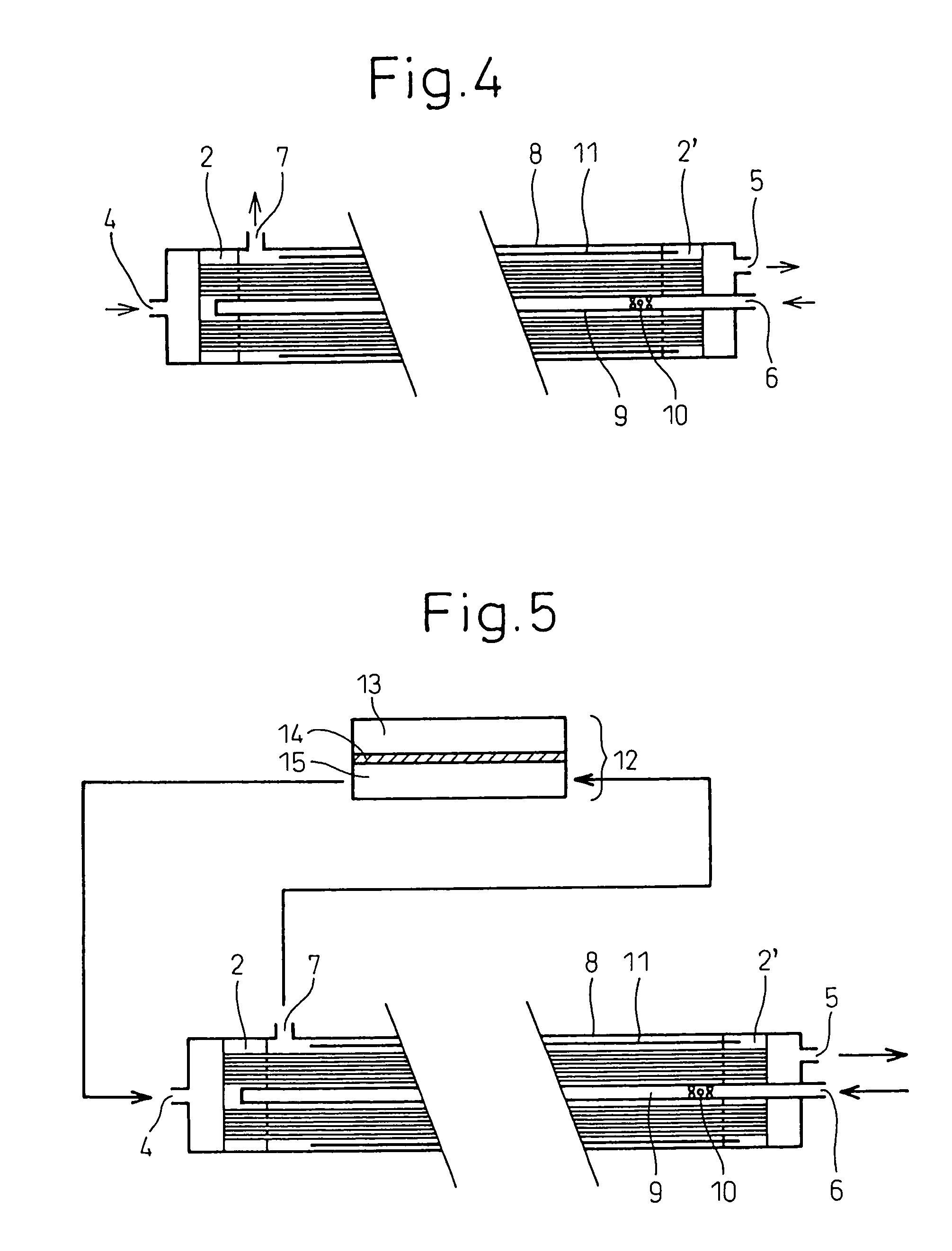
[0097]A hollow fiber membrane element using Polyimide Hollow Fiber Membrane A (inner diameter of hollow fiber membrane: 710 μm), where the effective length (L) of the hollow fiber membrane bundle was 360 mm (the length of each tubesheet was 50 mm, hereinafter the same), the membrane filling percentage was 40%, about 80% of the outer peripheral area of the hollow fiber membrane bundle was covered with a polyimide film along the outer circumference, and the inner diameter of the covering cylindrical film was 150 mm (D), was loaded into a cylindrical container having an inner diameter of 165 mm to produce a humidifying apparatus shown in FIG. 4 (L / D=2.4).

[0098]Air at almost atmospheric pressure, a temperature of 80° C. and a relative humidity of 95% was supplied as the first gas to the hollow side of the hollow fiber membrane 20 at a flow rate of 500 N liter / min, and air at almost atmospheric pressure, a temperature of 25° C. and a relative humidity of 10% was supplied as the second ga...

example 2

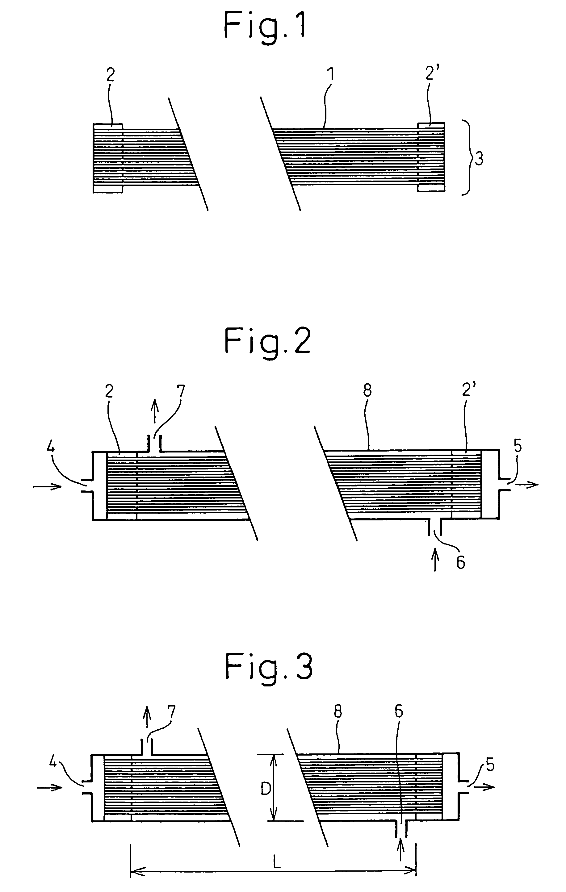
[0103]A hollow fiber membrane element using Polyimide Hollow Fiber Membrane A (inner diameter of hollow fiber membrane: 710 μm), where the effective length (L) of the hollow fiber membrane bundle was 600 mm and the membrane filling percentage was 40%, was loaded into a cylindrical container having an inner diameter of 200 mm (D) to produce a humidifying apparatus shown in FIG. 2 (L / D=3.0).

[0104]Air at almost atmospheric pressure, a temperature of 80° C. and a relative humidity of 95% was supplied as the first gas to the hollow side of the hollow fiber membrane at a flow rate of 1,500 N liter / min, and air at almost atmospheric pressure, a temperature of 25° C. and a relative humidity of 10% was supplied as the second gas to the space on the outer side of the hollow fiber membranes at a flow rate of 1,500 N liter / min. These first and second gases were supplied to countercurrently flow.

[0105]The pressure and dew point of each gas were measured. As a result, the pressure loss when the f...

example 3

[0109]A hollow fiber membrane element using Polyimide Hollow Fiber Membrane C (inner diameter of hollow fiber membrane: 570 μm), where the effective length (L) of the hollow fiber membrane bundle was 320 mm and the membrane filling percentage was 40%, was loaded into a cylindrical container having an inner diameter of 100 mm (D) to produce a humidifying apparatus shown in FIG. 2 (L / D=3.2).

[0110]Air at a pressure of 0.2 MPaG, a temperature of 80° C. and a relative humidity of 95% was supplied as the first gas to the hollow side of the hollow fiber membrane at a flow rate of 500 N liter / min, and air at a pressure of 0.2 MPaG, a temperature of 25° C. and a relative humidity of 5% was supplied as the second gas to the space on the outer side of the hollow fiber membrane at a flow rate of 500 N liter / min. These first and second gases were supplied to flow countercurrently.

[0111]The pressure and dew point of each gas were measured. As a result, the pressure loss when the first gas was flo...


PUM

PropertyMeasurementUnit
pressureaaaaaaaaaa
inner diameteraaaaaaaaaa

Abstract

An object of the present invention is to provide a humidifying apparatus capable of improving the humidification efficiency while lowering the pressure loss of gas even when a low-pressure gas is used, and is suitably usable for fuel cells. The present invention relates to a humidifying apparatus for fuel cells, fabricated by loading a hollow fiber membrane element into a container such that the space communicating with the hollow side of the hollow fiber membranes is isolated from the space communicating with the outer side of the hollow fiber membranes, wherein (a) the inner diameter of the hollow fiber membrane is larger than 400 μm, (b) the water vapor permeation rate (P′H2O) of the hollow fiber membranes is 0.5×10⁻³ cm3 (STP) / cm2·sec·cm Hg or more, (c) the ratio (P′H2O / P′O2) of the water vapor permeation rate to the oxygen gas permeation rate of the hollow fiber membranes is 10 or more, and (d) the elongation at tensile break of the hollow fiber membranes after hot water treatment in hot water at 100° C. for 50 hours is 80% or more of that before the hot water treatment; particularly, the present invention relates to a humidifying apparatus for fuel cells where, if the effective length of the hollow fiber membrane element is L and the inner diameter of the container into which the hollow fiber membrane element is loaded is D, L / D is 1.8 or more.

Description

TECHNICAL FIELD[0001]The present invention relates to a humidifying apparatus, using hollow fiber membranes, which is suitable for humidifying a supply gas of a fuel cell. The humidifying apparatus for fuel cells of the present invention can perform humidification with high efficiency while lowering a pressure loss, can reduce the permeation of components other than water vapor and is economical. Particularly, the humidifying apparatus for fuel cells of the present invention is suitable for recovering the water component from the exhaust gas discharged from a fuel cell and using it for humidifying a supply gas supplied to the fuel cell.BACKGROUND ART[0002]In recent years, a fuel cell using a solid polymer membrane, such as perfluorocarbonsulfonic acid membrane, for the electrolyte membrane is attracting attention as a power source of electric cars or small stationary power-generating devices. Such solid polymer functions, in the hydrous state, as a proton conductive electrolyte but ...

Claims


Application Information

Patent Timeline
Patent Type & Authority Patents(United States)
IPC IPC(8): B01F3/04H01M8/02
CPCH01M8/0291H01M8/04134H01M8/04149F24F2003/1435Y02E60/50H01M2008/1095H01M8/04141H01M8/0289
Inventor TANIHARA, NOZOMUYOSHINAGA, TOSHIMUNE
Owner UBE IND LTD
Why Eureka
Try Eureka