
Optical glass, preform for press molding and optical element

Inactive Publication Date: 2007-01-02
HOYA CORP
View PDF21 Cites 20 Cited by
  • Summary
  • Abstract
  • Description
  • Claims
  • Application Information

AI Technical Summary

Benefits of technology

[0014]Under the circumstances, it is an object of the present invention to provide an optical glass that is free of lead and fluorine, which has a low glass transition temperature permitting press-molding with a mold formed of stainless steel, and which has high climate resistance, a press-molding preform, which is formed of the above optical glass, and a process for the preparation thereof. Another object of the present invention is to provide an optical element formed of the above optical glass and a process for producing an optical element, which comprises press-molding the above preform.

Problems solved by technology

However, although a conventional ceramic mold material is excellent as a press mold material, the problem is that it is difficult to cut the ceramic mold material.
However, stainless steel is not durable against the temperature of 500° C. or higher that is required for press-molding a glass.
Further, when a mold formed of stainless steel is repeatedly used at a temperature of 400° C. or higher, the mold surface is roughened and becomes fragile, so that the stainless steel is unsuitable as a material for a mold for precision press-molding.
Attempts have been made to decrease the glass transition temperature to a great extent by incorporating lead, or attempts have been made to form a glass having a lower glass transition temperature by introducing fluorine, although these attempts have not been intended for using a press mold formed of stainless steel.
However, although lead is a component effective for decreasing the glass transition temperature, lead is a component whose use should be controlled for a reason that it causes a detrimental effect on environments.
Since fluorine exhibits high volatility at a high temperature, it causes striae due to volatilization when a press-molding preform is prepared from a molten glass, so that it is difficult to prepare a preform stably.
Further, a substance volatilized from a glass adheres to a press mold during press-molding, so that the substance decreases or degrades the form accuracy of the press mold.
In the glass disclosed in the above Publication, however, the amount of an alkali metal oxide as a component for decreasing the glass transition temperature is insufficient, so that it is difficult to decrease the sag temperature of the glass to 400° C. or lower.
When the glass described in the above Publication is press-molded, it is impossible to use a mold formed of stainless steel.
However, if the climate resistance of a glass is degraded as described above, the advantage of the glass over plastic materials is impaired.

Method used


Image

  • Optical glass, preform for press molding and optical element
  • Optical glass, preform for press molding and optical element

Examples


example 1

[0113]As raw materials for glass components, corresponding oxides, carbonates, sulfates, nitrates, phosphates, hydroxides, etc., in an amount of 250 to 300 g were weighed in predetermined amount ratios shown in Tables 1, 3 and 5 and fully mixed to prepare a formulated batch. The batch was placed in a platinum crucible and melted at 1,100 to 1,300° C. with stirring in air for 2 to 4 hours. After the glass was melted, a glass melt (molten glass) was cast into a 40×70×15 mm carbon mold and allowed to cool to a glass transition temperature. Immediately thereafter, the glass was placed in an annealing furnace, annealed around a glass transition temperature for about 1 hour and allowed to cool to room temperature in the annealing furnace. The thus-obtained glass was observed through a microscope, to show no precipitation of a crystal.

[0114]Each optical glass was measured for a refractive index (nd), an Abbe's number (νd), a glass transition temperature (Tg), a liquidus temperature (LT) an...

example 2

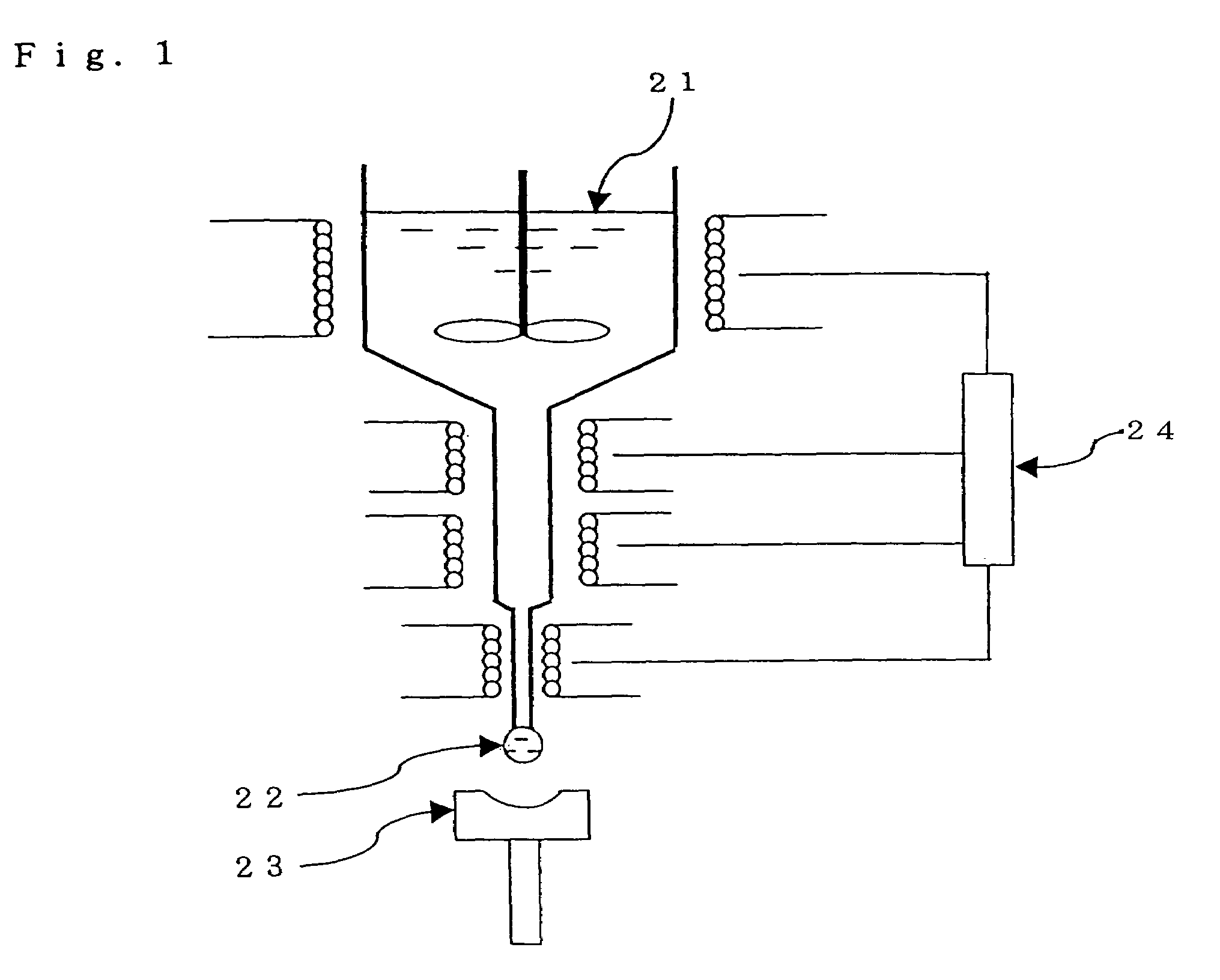
[0130]The optical glass obtained in Example 1 was shaped into spherical preforms having a diameter of 2 to 30 mm with a hot preform floating shaping apparatus shown in FIG. 1. The preforms were shaped so as to have weights equivalent to weights of press-molded products to be produced. FIG. 1 shows a schematic cross-sectional view of the preform shaping apparatus, in which numeral 21 indicates a molten glass, 22 indicates a glass drop, 23 indicates a preform-shaping mold, and 24 indicates a temperature-control portion.

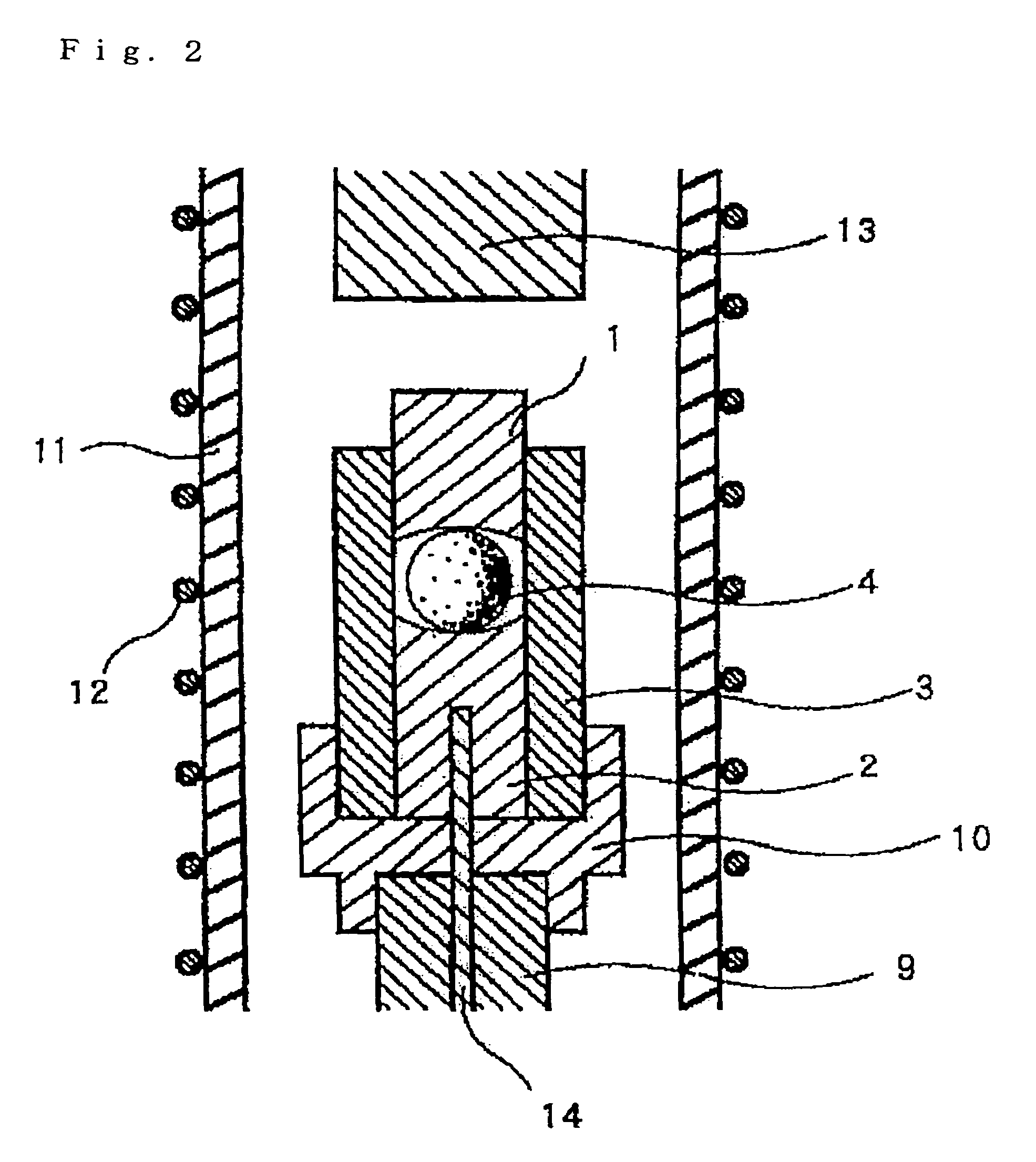
[0131]Then, the above preforms were molded as follows by means of a precision press-molding apparatus shown in FIG. 2. A preform 4 was placed between a lower mold member 2 formed of stainless steel having a spherical or aspherical surface form and an upper mold member 1 formed of stainless steel in the precision press-molding apparatus. An inside of a quartz tube 11 was filled with a nitrogen atmosphere, and a heater 12 is electrically powered to heat the inside of the ...

example 3

[0132]A pattern having an inversion form of a diffraction grating pattern was formed on a molding surface of a mold formed of stainless steel by cutting, and a press-mold consisting of a lower mold member and an upper mold member was prepared.

[0133]A preform that was the same as a preform used in Example 2 was press-molded under the same conditions as those in Example 2, whereby a diffraction grating was obtained. In this manner, excellent diffraction gratings were obtained.


PUM

PropertyMeasurementUnit
Temperatureaaaaaaaaaa
Fractionaaaaaaaaaa
Fractionaaaaaaaaaa

Abstract

An optical glass being free of lead and fluorine, having a low glass transition temperature permitting press-molding with a mold formed of stainless steel and having high climate resistance includes an optical glass comprising, by mol %, 25 to 44% of P2O5, 10 to 40% of a total of Li2O, Na2O and K2O, 5 to 40% of ZnO, 1 to 35% of BaO and at least one components selected from Nb2O5, Bi2O3 and WO3, having a glass transition temperature (Tg) of 370° C. or lower and being free of lead and fluorine and an optical glass which is free of lead and fluorine, has a mass loss ratio of less than 0.25% when immersed in pure water, and has a glass transition temperature (Tg) of 370° C. or lower.

Description

[0001]This application claims priority to Japan Application No. 2002-380540, filed 27 Dec. 2002. The entire contents of this application are incorporated herein by reference.BACKGROUND OF THE INVENTION[0002]1. Field of the Invention[0003]The present invention relates to an optical glass, a preform for press-molding (a press-molding preform), a process for preparing the preform, an optical element and a process for producing the optical element. More specifically, the present invention relates to an optical glass that is free of lead and fluorine, which has a low transition temperature compatible with molding with a mold formed of stainless steel and which has high climate resistance, a press-molding preform formed of the above optical glass, a process for preparing the preform, an optical element formed of the above optical glass and a process for producing an optical element by press-molding the above preform.[0004]2. Prior Art[0005]Generally, a method of precision press-molding of...

Claims


Application Information

Patent Timeline
IPC IPC(8): C03C3/16C03C3/19C03C3/21
CPCC03C3/21C03C3/16
Inventor KASUGA, YOSHIKOZOU, XUELU
Owner HOYA CORP
Learn More