
Apparatus and method for performing radiation energy treatments

a radiation energy treatment and apparatus technology, applied in the field of apparatus and methods for performing radiation energy treatment, can solve the problems of difficult accurate control, varies in the angle between the discharge end of such wand-like devices and the surface exposed, and the area exposed to laser energy is often difficult to accurately control, so as to achieve the effect of greater treatment area coverag

Inactive Publication Date: 2007-01-09
SIEGEL JERRY
View PDF11 Cites 28 Cited by
  • Summary
  • Abstract
  • Description
  • Claims
  • Application Information

AI Technical Summary

Benefits of technology

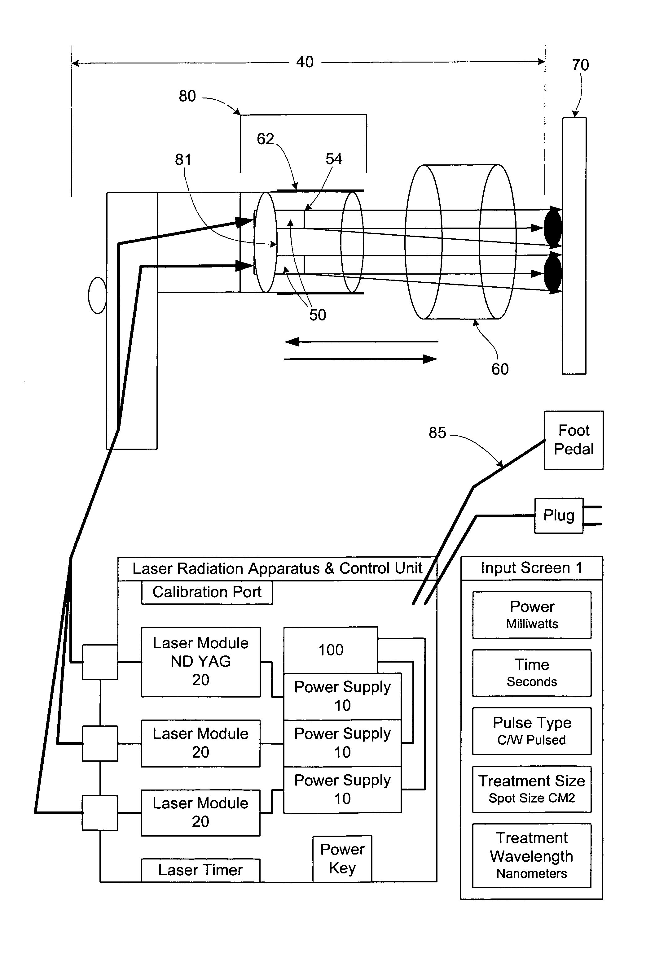
[0012]The present invention is directed to an apparatus and a method for performing non-invasive and invasive radiation energy treatments, including at least photo-stimulation, biostimulation, and / or photocollagen stimulation, on biological tissue. The apparatus includes at least one, but preferably a plurality of radiation energy sources structured to selectively emit radiation towards the biological tissue. The apparatus further includes an irradiation head assembly which includes an adjustable collector assemble structured to collect and redirect scattered and reflected radiation back to the treatment site, an adjustable collimator assembly structured to adjustably collimate the emitted radiation, and an adjustable focal length setting mechanism structured to securely set a desired focal length of the emitted radiation relative to the biological tissue. The apparatus may further include one or more beam splitter assemblies to either allow for greater treatment area coverage or for the purpose of treating two patents requiring the same treatment protocol simultaneously while employing only a single radiation energy source. Furthermore, this apparatus may include a multi-fiber array or a conventional laser combiner to either marry a plurality of different wavelengths or utilize the different wavelengths individually depending upon the requirements of the treatment modality, tissue type, and the specific treatment protocol required.
[0015]The present invention further provides that the emitted radiation is disposed relative to a transmission assembly, wherein the transmission assembly comprises an elongated configuration structured to direct substantially all of the radiation emitted from the plurality of the radiation energy sources to the biological tissue. The transmission assembly includes at least one, but preferably a plurality of fiber optic cables which must be at least equal in number to the number of radiation energy sources. The plurality of fiber optic cables of the transmission assembly are further disposed together in a single bundle. Each fiber optic cable has a proximal end and a distal end, wherein each proximal end is operatively associated with and disposed to receive the radiation emitted from one of the plurality of radiation energy sources. The distal end of each fiber optic cable is structured to terminate at a point proximate to the biological tissue. Further, each fiber optic cable is structured to receive the radiation emitted from no more than one radiation energy source at one time so the amount and wavelength of the radiation emitted to the biological tissue may be precisely controlled.
[0016]An illustrated embodiment of the present invention includes an irradiation head assembly which may comprise the adjustable collector assembly, the adjustable collimator assembly, and the adjustable focal length setting mechanism. The illustrated adjustable collector assembly includes a reflecting device or lens at the posterior of the assembly that facilitates in the reshaping and redirection of the reflected and scattered treatment radiation back onto the site of treatment. The entire collection assembly by shape form and function, increases the effectiveness of the radiation treatment by redirecting treatment radiation that would normally be lost and by increasing the safety for all who are in the treatment room by eliminating the risk of eye damage due to scattered or reflected radiation. The illustrated adjustable collimator assembly of the present invention includes an inlet aperture and an outlet aperture, the inlet aperture being structured to engage the distal end of each fiber optic cable of the transmission assembly. Moreover, the adjustable collimator assembly may include at least one, but preferably a plurality of adjustable collimators. Additionally, the adjustable collimator assembly of the present invention is preferably articulating and targetable. In at least one embodiment, the plurality of adjustable collimators are preferably disposed to engage one another in a series configuration, so that the combined radiation emitted from the plurality of radiation energy sources is collimated by the first collimator, which is further collimated by the second collimator, and continuing in a similar fashion through each adjustable collimator. Accordingly, an illustrated embodiment of the present invention includes a plurality of adjustable collimators engaged in series so the radiation emitted from the plurality of radiation sources may be adjustably collimated over a continuous range.
[0017]The irradiation head assembly may further comprise an adjustable focal length setting mechanism, which operatively engages the outlet aperture of the adjustable collimator assembly. Thus, in addition to the collimation of the radiation emitted from one or more radiation sources, the focal length of the emitted radiation beam may be adjusted and set to define a specific contact area or “spot size”, prior to exposure of the biological tissue. The adjustable focal length setting mechanism is structured to set a plurality of focal lengths between the outlet aperture of the adjustable collimator assembly and the contact surface of the adjustable focal length setting mechanism. Further, the contact surface is structured to be disposed in direct contact with the patient, and typically in direct contact with the biological tissue being treated, except, of course, when subcutaneous treatment is being performed, in which case the biological tissue being treated may not be directly contacted. Thus, each of the plurality of focal length settings, in conjunction with the adjustment of the collimation and the angle at which the beam is transmitted, defines a specific contact area or “spot size” on the contact surface. This is partly due to the fact that once a focal length is set, the distance between the outlet aperture and the contact surface is a fixed value. In a preferred embodiment of the present invention, the adjustable focal length setting mechanism is structured to set a plurality of focal lengths over a continuous range. The adjustable focal length setting mechanism thus provides a means to adjust and set the contact area or “spot size” of the combined emitted radiation, thus allowing the energy density to be precisely controlled during exposure of the biological tissue, which permits treatment over a larger “spot size” than would safely be possible otherwise. Indeed, the ultimate adjustment of the adjustable collimator and the adjustable focal length setting mechanism may utilize high power lasers and convert their ablative energy, thereby providing either biostimulation, photo-stimulation, or photocollagen stimulation by reducing the energy density via an increase in the divergence of the laser beam, and, therefore, the “spot size” at the affected area, thus providing a safe and desired energy density.

Problems solved by technology

In addition to the variability present in laser energy output and energy wavelength, perhaps the most critical variable in the medical application of laser beams, and among the most difficult to accurately control, is the energy density at the point of exposure of the biological tissue.
Even in the hands of the skilled medical laser operator, however, the distance and angle between the discharge end of such wand-like devices and the surface exposed are not precisely maintained, therefore, the area exposed to the laser energy often varies.
Further, even when a fixed laser beam is employed, control of the area exposed is difficult and imprecise.
First, the patient must be positioned the exact and correct distance from the laser beam to define the area of exposure, which is difficult to do with precision due to the distance between the laser beam and the patient.
In addition, the patient must be positioned such that the area exposed is at the correct angle relative to the fixed laser beam, again being difficult to do with precision due to the distance between them.
As may be appreciated, the control of the area exposed, and thus, the energy density to which biological tissue is exposed, by either of the above techniques is difficult at best.
Indeed, partly for this reason, known systems are configured to only treat very small areas, making the procedures very time consuming and as a result, more susceptible to error.
Furthermore, no one has described an apparatus that incorporates a device that comprises a collector with a reflecting lens that collects and then redirects the scattered and reflected radiation back to the site of treatment while utilizing either a single collimator or multiple collimators that are targetable and focusable and that include an adjustable focal length mechanism that emit coincident visible and infrared radiation, that can either intersect inside the targeted tissue or deploy in series upon the tissue, wherein the infrared radiation has a wavelength of approximately 1110 nm.

Method used


Image

  • Apparatus and method for performing radiation energy treatments
  • Apparatus and method for performing radiation energy treatments
  • Apparatus and method for performing radiation energy treatments

Examples


Embodiment Construction

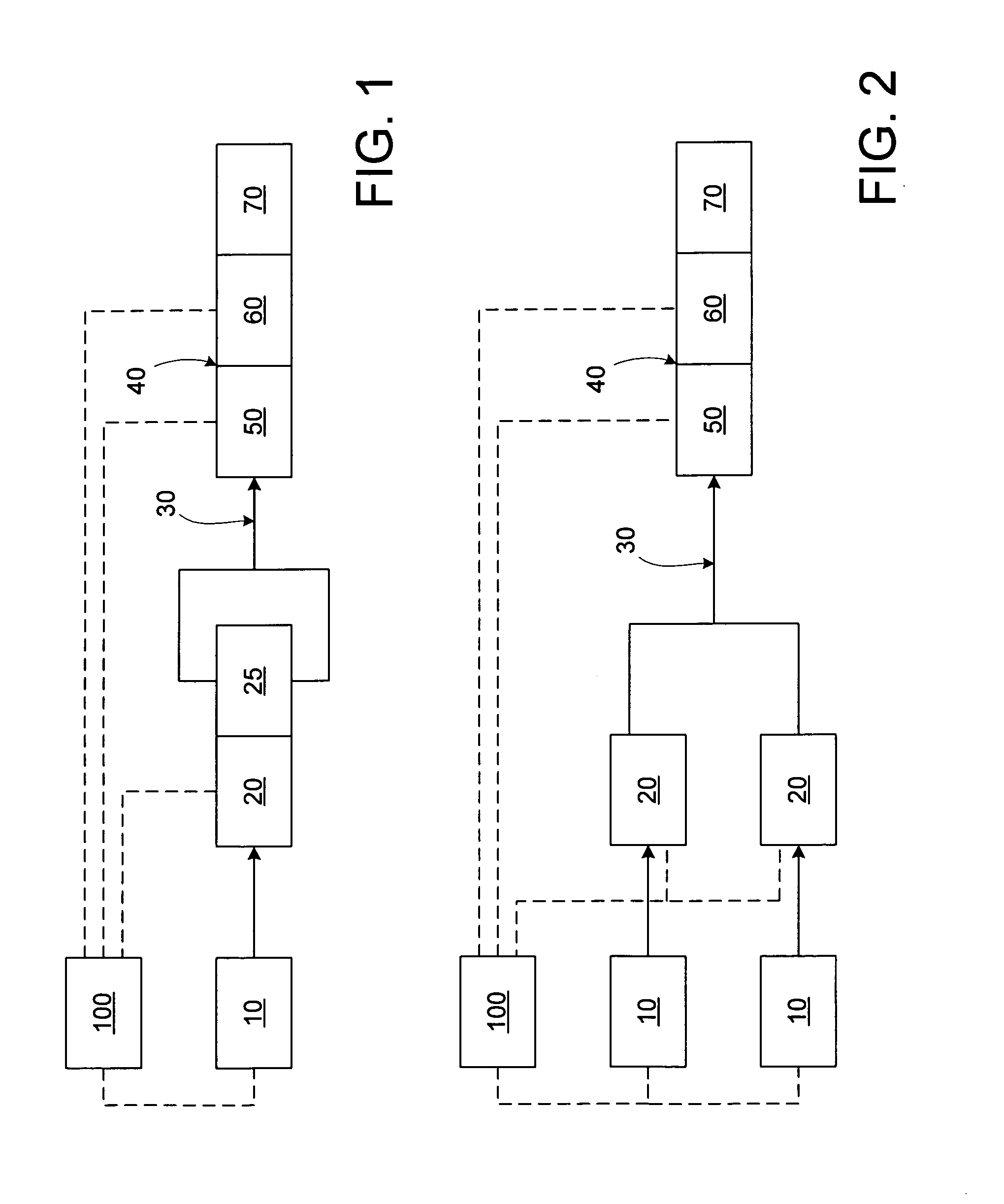
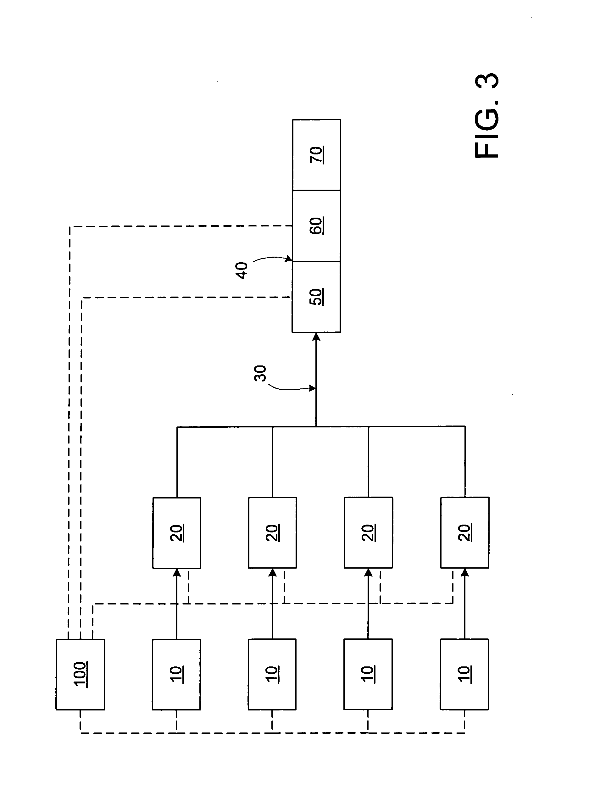
[0034]As shown throughout the Figures, the present invention is directed to an apparatus and method for performing a plurality of radiation energy treatment, including at least photo-stimulation, biostimulation, photocollagen stimulation, and / or photobiostimulation, on biological tissue. The apparatus provides complete control of the energy density, area of treatment or “spot size”, and allows the utilization of specific wavelengths alone or in combination, either coincidentally or adjacently, as required for optimal penetration and absorption characteristics to selectively treat a specific tissue type and obtain the most beneficial results. As shown in FIG. 1, the laser treatment apparatus includes a power supply, which is shown schematically as 10, for at least one radiation energy source, shown schematically as 20, wherein the radiation energy output by the radiation energy source 20 is received by a transmission assembly, generally shown as 30, which transmits the radiation ener...


PUM


Abstract

An apparatus and method to apply photo-stimulation, photo-dynamic therapy and / or ablation laser treatment to biological tissue. The apparatus includes a plurality of radiation energy sources, preferably laser beams. Additionally, the apparatus allows either a single wavelength or a combination of various wavelengths, either coincidentally or adjacently, to be utilized to achieve a desired treatment effect. Laser beams are transmitted to the treatment area by one or more fiber optic cables which terminate at an assembly structured to collimate the emitted radiation prior to application to the tissue. In addition, the apparatus includes a focal length setting mechanism which assures that a constant, fixed distance exists between the point of discharge of the laser beam and the biological tissue, thus assuring a constant energy density at the point of application. A method is presented for applying photo-stimulation, photocollagen stimulation and / or ablation laser treatment utilizing the above apparatus.

Description

[0001]This application relates back to Provisional Patent Application jc879 U.S.PTO 60 / 314,938—Filed on Aug. 23, 2001BACKGROUND OF THE INVENTION[0002]1. Field of the Invention[0003]The present invention is directed to an apparatus and a method for performing radiation energy treatment on a target area of biological tissue, wherein the apparatus for performing radiation energy treatments on biological tissue is structured to provide a plurality of laser energy treatments comprising of at least but not limited to ablation, biostimulation, photo-stimulation, photocollegan regeneration, and photo-dynamic therapy, either separately or in conjunction with one another, utilizing low, medium, and / or high power lasers employing either a single wavelength or combining various wavelengths, either coincidentally or adjacently, for a specific desired effect in a safe and controlled manner that allows for a larger and more effective contact area to be defined by effectively controlling the energy...

Claims


Application Information

Patent Timeline
IPC IPC(8): A61B18/18
CPCA61B18/203A61N5/0616A61B2018/00452A61B2018/207A61N2005/0644A61N5/062A61N2005/063
Inventor SIEGEL, JERRY
Owner SIEGEL JERRY
Learn More