
Closed molding tool

a closed molding and tool technology, applied in the field of fiber reinforced composite components production, can solve the problems of less consistent part quality in high volume production, less open molding lamination process, and falling out of favor of manufacturers, and achieve the effect of facilitating the movement of resin

Active Publication Date: 2007-01-09
TRACKER MARINE LP
View PDF36 Cites 30 Cited by
  • Summary
  • Abstract
  • Description
  • Claims
  • Application Information

AI Technical Summary

Benefits of technology

"The patent describes a flexible molding component that can be used to make fiber reinforced composite parts. This component has a flexible body structure with a perimeter seal that can be sealed to the base mold. The tool has resin and vacuum distribution channels to deliver resin to the fiber lay up and draw it through the lay up. The flexible body structure can be made of materials like polyurea or polyurethane and has advantages such as reusability, flexibility, and high tolerance flexibility. The molding process is closed, reducing expense and labor, and the resulting parts have better structural integrity. The flexible molding component can be used with many existing open molding tools without the need for modifications. The molding tool is compatible with various resins and can be easily repaired. The parts can be used in industries like marine, automotive, recreational vehicle, and aircraft."

Problems solved by technology

Apart from these similarities, however, molding processes are distinct in the efficiencies provided by each, as well as in the disadvantages or tradeoffs encountered when choosing a molding process for fabricating a specific type or run of a component.
Open molding lamination processes are traditionally more labor intensive than other molding processes and usually produce less consistent part quality in high volume production.
Open molding processes are also falling out of favor with manufacturers due to the high emissions of volatile organic compounds (VOC) realized in part production.
One proposed solution was to use component materials that resulted in fewer VOC emissions, but this has resulted in parts having poor physical characteristics.
Still, despite these disadvantages, open molding processes—along with vacuum bag molding—are generally the only widely used molding processes that are capable of producing low volume or low run parts in a cost effective manner.
When using a disposable vacuum bag, a peel ply release film and a resin flow / bleeder media must often be stacked atop the fiber lay up below the bag because of the nature of the thin sheet film to conform very tightly to the fiber layer up and make resin flow very difficult.
Despite the high quality of the part produced using disposable vacuum bag molding techniques (i.e., having a high fiber to resin ratio), certain disadvantages are apparent.
For example, many of the aforementioned components used in disposable vacuum bag techniques—including the vacuum bag having resin and vacuum supply lines integrally formed therewith, the resin flow / bleeder media, the peel ply film, the resin and vacuum distribution lines and the adhesive sealant tape—are disposed of after molding only a single part, making this technique prohibitively expensive for all but high margin parts manufacturing.
Furthermore, if the female mold has a complex shape, many pieces of sheet film may need to be cut and bonded together with sealant tape to produce a bag with the desired shape, thereby significantly increasing manufacturing time per part as compared to open molding processes.
The silicone bag is typically fabricated from silicone sheet or a brushable silicone liquid, but because silicone alone usually does not have enough strength to withstand the vacuum draw in the molding process, a reinforcement such as nylon mesh or other materials is often laminated with the silicon.
Another problem with silicone is that even with a reinforcement, the bag tends to have a relatively short life and is useful for only small part production runs; the silicone bag is easily damaged in the production environment, difficult to have resin and vacuum supply and distribution lines integrated therewith, and tends to expand dimensionally over a number of production runs, requiring significant maintenance to keep the bag usable for the molding process.
Silicone materials are also expensive, leading to a high initial cost of fabricating the vacuum bag.
Also, silicone bags require oven curing in the fabrication of the more durable materials, which adds further to the cost of the process with the additional time, energy and equipment requirements.
One significant disadvantage of resin transfer molding, however, is that because the male and female molds are rigid, if the fiber load of the lay up is not precisely the correct quantity at the correct position, structural weakness in the part occur.
Both dry spots and resin filled spots in finished parts are susceptible to fracture or other structural failures at relatively low force loads.
These structural weaknesses are even more important when fabricating large parts, such as boat hull components, where the weight of the part itself may facilitate structural failures.
Matched, rigid tooling is very expensive to produce and, therefore, the process is less amenable to changes that may be required for structural, process, or styling updates.
Current closed molding lamination techniques do not provide an economical and reliable solution for fabricating fiber reinforced composite parts, especially with respect to small to medium part runs.

Method used


Image

  • Closed molding tool
  • Closed molding tool
  • Closed molding tool

Examples


Embodiment Construction

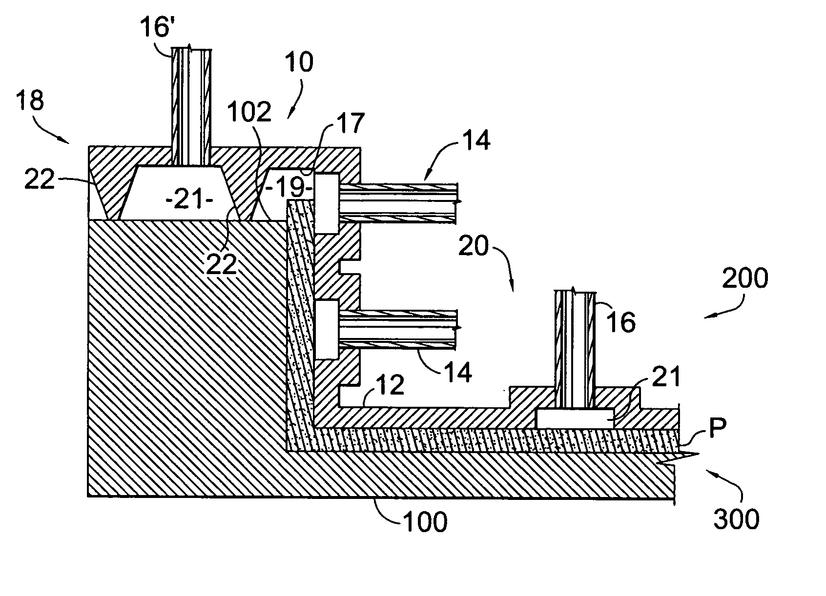
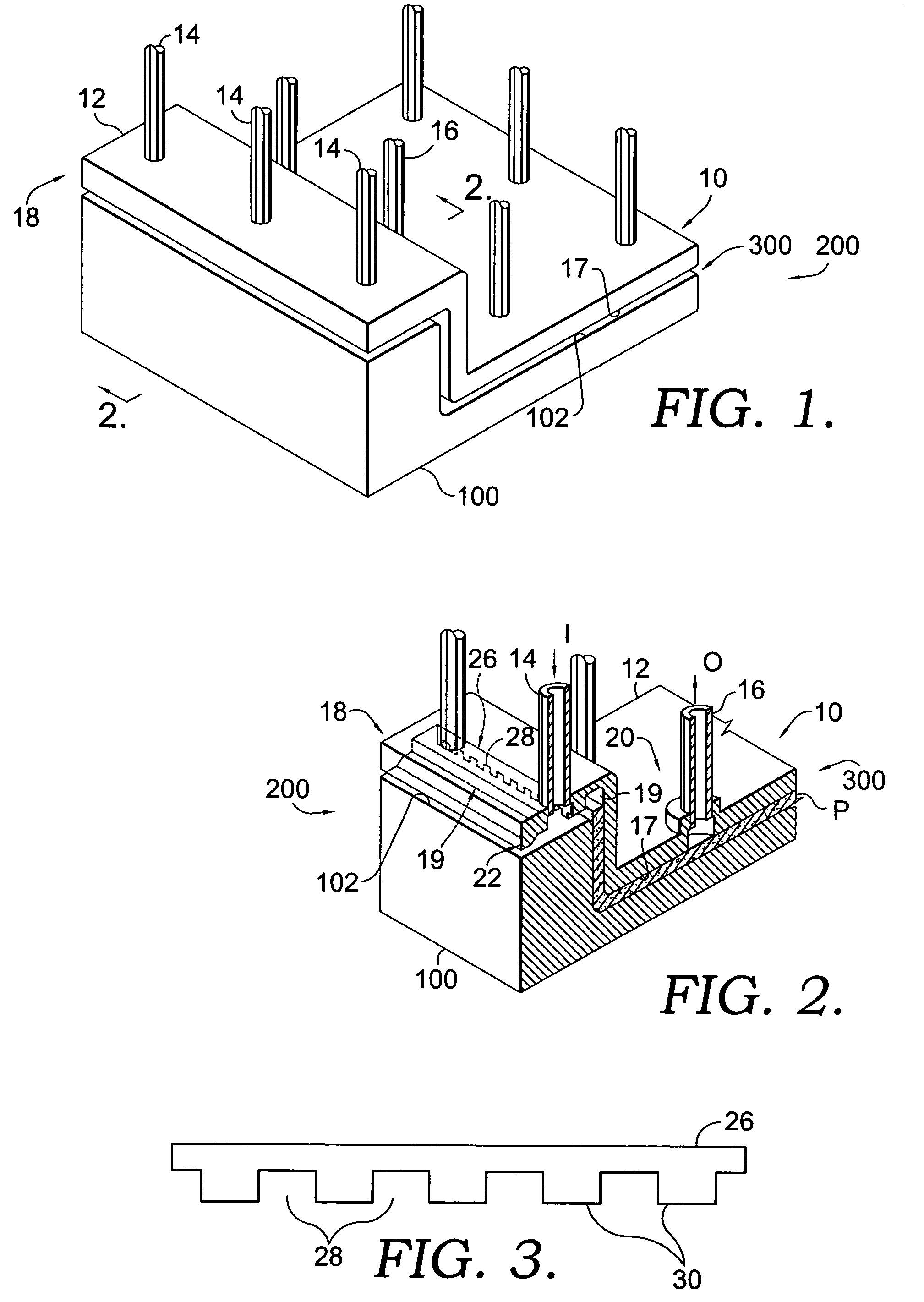
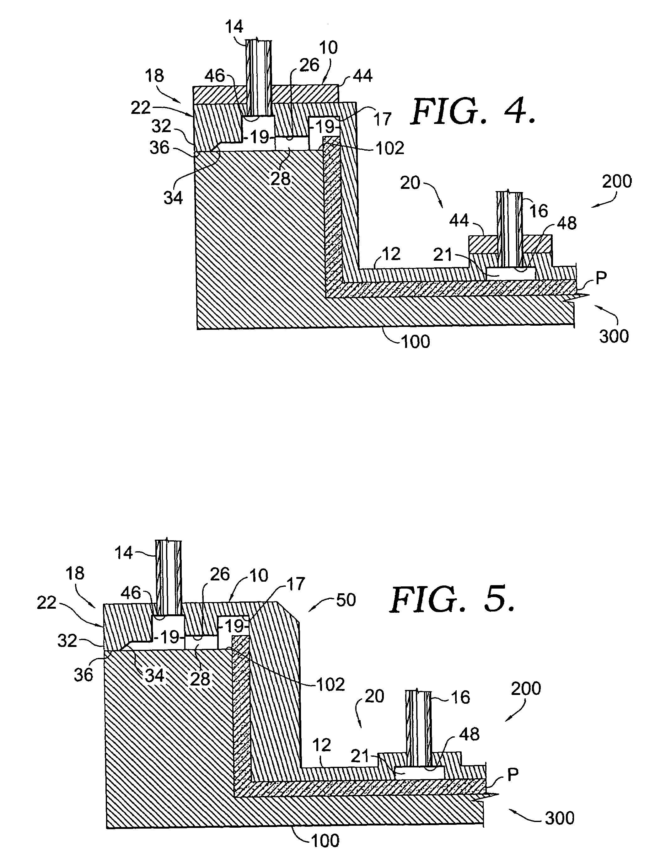
[0021]The present invention improves on the materials and techniques implemented in traditional vacuum bag molding by providing, in a closed molding process, a flexible molding component or tool configured for use with a base mold tool to form a fiber reinforced composite part. With reference to FIG. 1, a flexible molding component 10 is shown in use with a base mold 100—in this particular example, a rigid female mold—to form a closed molding tooling system 200 for part fabrication. The base mold 100 may also be referred to as an “A” surface tool while the molding component 10 may also be referred to as a “B” surface tool, regardless of which surface tool would be considered either a male mold or a female mold is a specific tooling configuration.

[0022]The molding component 10, seen in more detail in FIG. 2, is formed of a flexible body structure 12 having integrally formed therewith one or more resin input ports 14 for delivering resin (e.g., polyester resin) to an enclosed space 30...


PUM

PropertyMeasurementUnit
flexibleaaaaaaaaaa
rigidityaaaaaaaaaa
physical propertiesaaaaaaaaaa

Abstract

A flexible molding component used with a base mold improves on existing methods of forming fiber reinforced composite parts. The molding component is formed of a flexible body structure having an interfacing surface and a perimeter region including a perimeter seal configured for sealing engagement with the base mold. Resin and vacuum distribution channels are formed in the interfacing surface to deliver resin to a fiber lay up disposed on the base mold and draw the resin across and through the lay up, respectively, to properly mix the resin / fiber combination which forms the desired part. Application of the vacuum causes the perimeter seal of the flexible body structure to sealingly engage with the base mold to enclose materials between the body structure and the mold, as well as causing the interfacing surface to draw against the resin / fiber combination and the mold to shape the combination into the desired part.

Description

CROSS-REFERENCE TO RELATED APPLICATIONS[0001]None.STATEMENT REGARDING FEDERALLY SPONSORED RESEARCH OR DEVELOPMENT[0002]Not Applicable.BACKGROUND OF THE INVENTION[0003]The production of fiber reinforced composite components, and in particular those components formed of a fiber / resin combination, have traditionally been accomplished by a number of open and closed molding lamination processes, or variations of each. Examples of these components include those used in the boating industry; such as fiber reinforced plastic sheets and parts with a compound shape used to manufacture a hull for a watercraft. These molding processes all involve a fiber reinforcement (e.g., fiberglass pieces) being laid up against a mold (e.g., a female mold) that provides the desired shape for the component, and the impregnation of the fiber with resin or a similar material. After curing, the resin / fiber combination forms a finished part that can be removed from the mold. Apart from these similarities, howeve...

Claims


Application Information

Patent Timeline
Patent Type & Authority Patents(United States)
IPC IPC(8): B29C70/44B29C41/08B29C70/36
CPCB29C70/548B29C70/443B29C70/544
Inventor MATAYA, ROBERT F.
Owner TRACKER MARINE LP
Learn More