CIC qam modulator

a qam modulator and cic technology, applied in the field of digital signal processing, can solve the problems of speed and quality of signal demodulation that are not optimized, and achieve the effect of increasing the speed of operation of the cic interpolator

Inactive Publication Date: 2007-01-09
REMEC BROADBAND WIRELESS NETWORKS LLC
View PDF4 Cites 12 Cited by
  • Summary
  • Abstract
  • Description
  • Claims
  • Application Information

AI Technical Summary

Benefits of technology

[0013]In one embodiment of the present invention, the CIC Interpolator further includes a plurality of pipeline registers. Each pipeline register i

Problems solved by technology

However, if each digital modem utilizes different sample clock signals, the modem architecture invol

Method used


Image

  • CIC qam modulator
  • CIC qam modulator
  • CIC qam modulator

Examples


Embodiment Construction

[0035]Reference will now be made in detail to the preferred embodiments of the invention, examples of which are illustrated in the accompanying drawings. While the invention will be described in conjunction with the preferred embodiments, it will be understood that they are not intended to limit the invention to these embodiments. On the contrary, the invention is intended to cover alternatives, modifications and equivalents that may be included within the spirit and scope of the invention as defined by the appended claims. Furthermore, in the following detailed description of the present invention, numerous specific details are set forth in order to provide a thorough understanding of the present invention. However, it will be obvious to one of ordinary skill in the art that the present invention may be practiced without these specific details. In other instances, well known methods, procedures, components, and circuits have not been described in detail as not to unnecessarily obsc...


PUM


Abstract

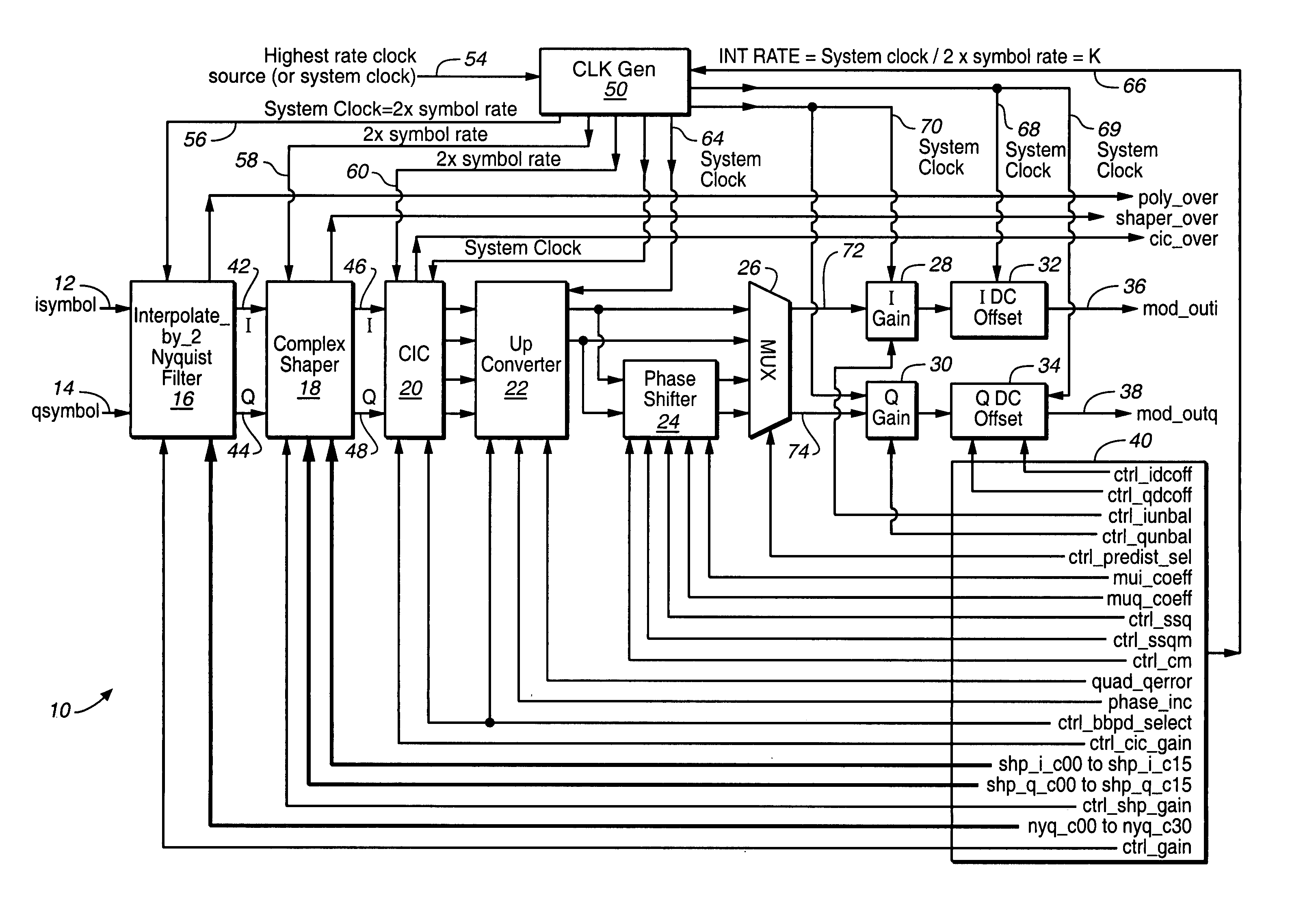
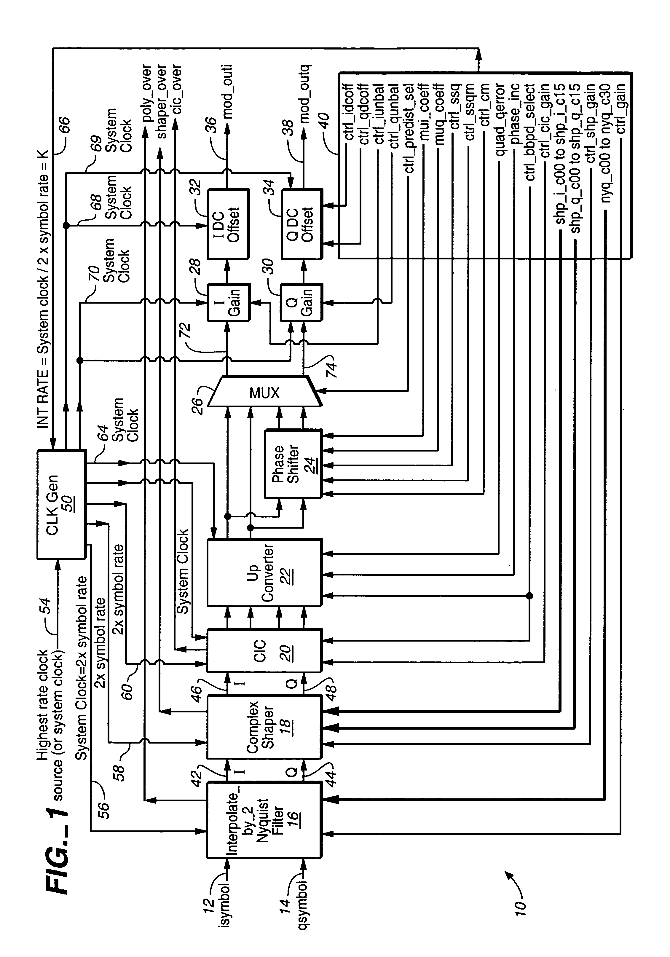
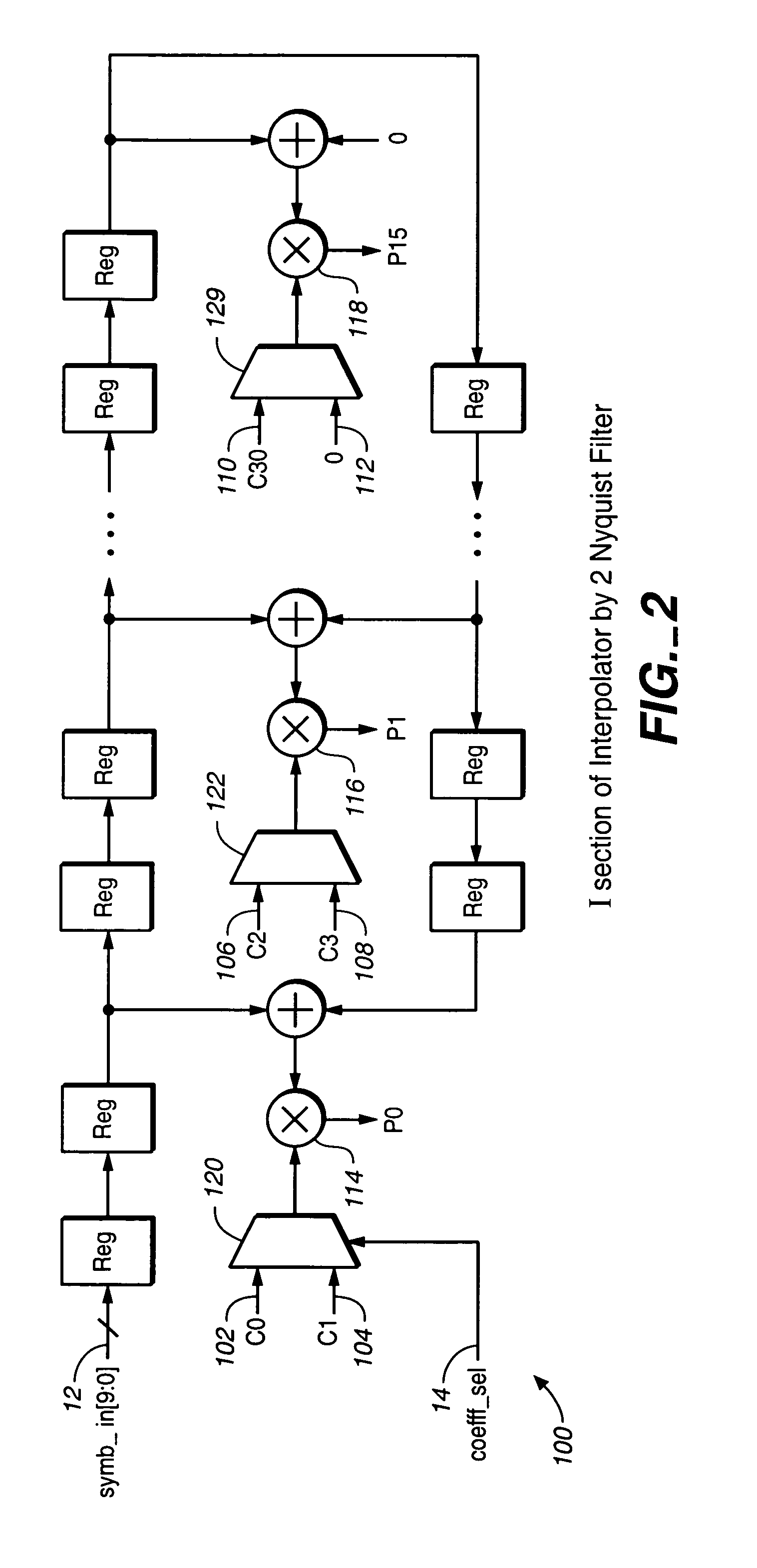
An apparatus for modulating a digital input signal having a pre-assigned symbol rate and having a baseband carrier frequency by using a single sample clock signal. The pre-assigned symbol rate is selected from the group consisting of a plurality of symbol rates. The apparatus in a baseband mode comprises: (a) an Interpolate_by_2_Nyquist Filter block configured to double the pre-assigned symbol rate, to perform Nyquist filtering operation, and configured to output an Inphase (I) and a Quadrature (Q) components of the pre-assigned signal having the double symbol rate; (b) a Complex Shaper block configured to pre-compensate the spectrum of I and Q components of the signal having the double symbol rate in advance for a spectrum distortion caused by the apparatus; ©) a Cascaded Integrated Comb (CIC) Interpolator filter configured to increase by an interpolation R factor the sample rate of the signal as compared with a sample rate of the baseband carrier; (d) a Phase Shifter configured to compensate a phase of interpolated by R signal for a known quadrature error; (e) an Inphase (I) channel and Quadrature (Q) channel Gain blocks configured to pre-compensate the I and Q components of the interpolated by R signal for a known gain difference circuit between the I and Q channel gains; (f) an I and Q channel DC offset blocks configured to pre-compensate I and Q components of the interpolated by R signal for a known DC offset difference circuit between I and Q channel DC offset blocks; and (g) a Controller block configured to supply a plurality of control signals to the apparatus. In the passband mode, I and Q channel Gains are set to one, and I and Q channel DC offsets are set to zero.

Description

BACKGROUND OF THE INVENTION[0001]1. Field of the Invention[0002]The present invention relates to the field of the digital signal processing, and more specifically, to the field of digital modulators.[0003]2. Discussion of the Prior Art[0004]When a plurality of symbol rates are used by transceivers of digital signals, each transceiver should be capable of multi-rate operations with different symbols rates. However, if each digital modem utilizes different sample clock signals, the modem architecture involves complicated analog components, and the speed and quality of signal demodulation is not optimized.[0005]What is needed is to design a digital modem that allows multi-rate operations with different symbol rates, but that utilizes a single sample clock signal, thus reducing the complexity of analog components and increasing the speed of signal acquisition and signal processing.SUMMARY OF THE INVENTION[0006]To address the shortcomings of the available art, the present invention provi...

Claims


Application Information

Patent Timeline
IPC IPC(8): H04L27/04
CPCH03C3/40H04L27/364H04L27/362H04L25/05
Inventor ISAKSEN, DAVID BRUCEFONG, MARK
Owner REMEC BROADBAND WIRELESS NETWORKS LLC
Why Eureka
Try Eureka