Energy-saving method for the wireless reception of data modulated on a carrier signal

a data modulation and energy-saving technology, applied in the field of energy-saving methods for the wireless reception of data modulated on a carrier signal, can solve the problems of low current consumption, inability to achieve maximum sensitivity in an interference-free environment, and inability to correct the reception of useful signals with an increased bit error rate, etc., to achieve the effect of reducing current consumption

Active Publication Date: 2007-01-09
VISHAY SEMICON
View PDF10 Cites 4 Cited by
  • Summary
  • Abstract
  • Description
  • Claims
  • Application Information

AI Technical Summary

Benefits of technology

[0006]The object of the invention is to provide an energy-saving method for operating such a receiver circuit which avoids the above-mentioned disadvantages—that is which leads to the same receiver properties which correspond to those of receivers which are in continuous operation—and with which a substantially reduced current consumption is nevertheless achieved.
[0008]After this, the receiver circuit in intermittent operation is not completely disconnected from the operating voltage source, but only the relevant circuit elements of the receiver, namely those which recover the data from the carrier signal, that is the input stage, amplifier stages, band filter and demodulator in particular On the other hand, those circuit elements which, for example, adapt the amplifier settings to the environment are uninterruptedly supplied with electrical energy, and as a consequence of the continuous supply of the operating voltage this information is not lost, so that, upon a renewed start up, work may continue with these parameters in the energy supply phase of the intermittent operation of the receiver without needing time for renewed tuning in to the optimal gain properties. A substantial reduction of the current consumption can be achieved by means of this intermittent operation with the same performance as comparable, known receivers operated in continuous reception operation, as a result of which, with a reduction of the current from 1 mA to 15 μA for example, battery driven applications can easily be realized.
[0011]The wake up and shut down modes can run automatically in an advantageous manner by means of the charging and discharging processes of an electrical storage element, preferably by means of a capacitor. In wake up mode, an incoming data signal is automatically detected and the receiver (i.e. the first group of circuit elements) remains in wake up mode, that is ready to receive. After processing the received signals and a renewed waiting time, the first group of circuit elements changes back into shut down mode. The size of the electrical storage element, that is the size of a capacitor for example, enables the pulse duty ratio of the intermittent operation to be freely selected, so that shut down phases of various lengths can be set which determine the duration of the start signal (pre-burst). Consequently, it is possible to weight the average current consumption in respect of the response time appropriately for the desired application. A unidirectional link to the microprocessor is sufficient as this method works autonomously by means of the storage element.

Problems solved by technology

If the interference environment here is, on the one hand, too great, so that the amplifier setting is too high for this environment after the POR, the correct reception of useful signals is only possible with an increased bit error rate.
On the other hand, the maximum sensitivity cannot be attained in an interference-free environment.
This known receiver operated in this manner may well have a sufficiently low current consumption, however the settings which determine the properties of the receiver or the gain properties are lost because of the cyclical disconnection of the source of energy, as a result of which the receiver has to work with the starting state again, which may have either a less sensitive, i.e. a reduced range, or a too sensitive setting, i.e. an increased bit error rate.
The area of application of such a receiver is thus severely limited.

Method used


Image

  • Energy-saving method for the wireless reception of data modulated on a carrier signal
  • Energy-saving method for the wireless reception of data modulated on a carrier signal
  • Energy-saving method for the wireless reception of data modulated on a carrier signal

Examples


Embodiment Construction

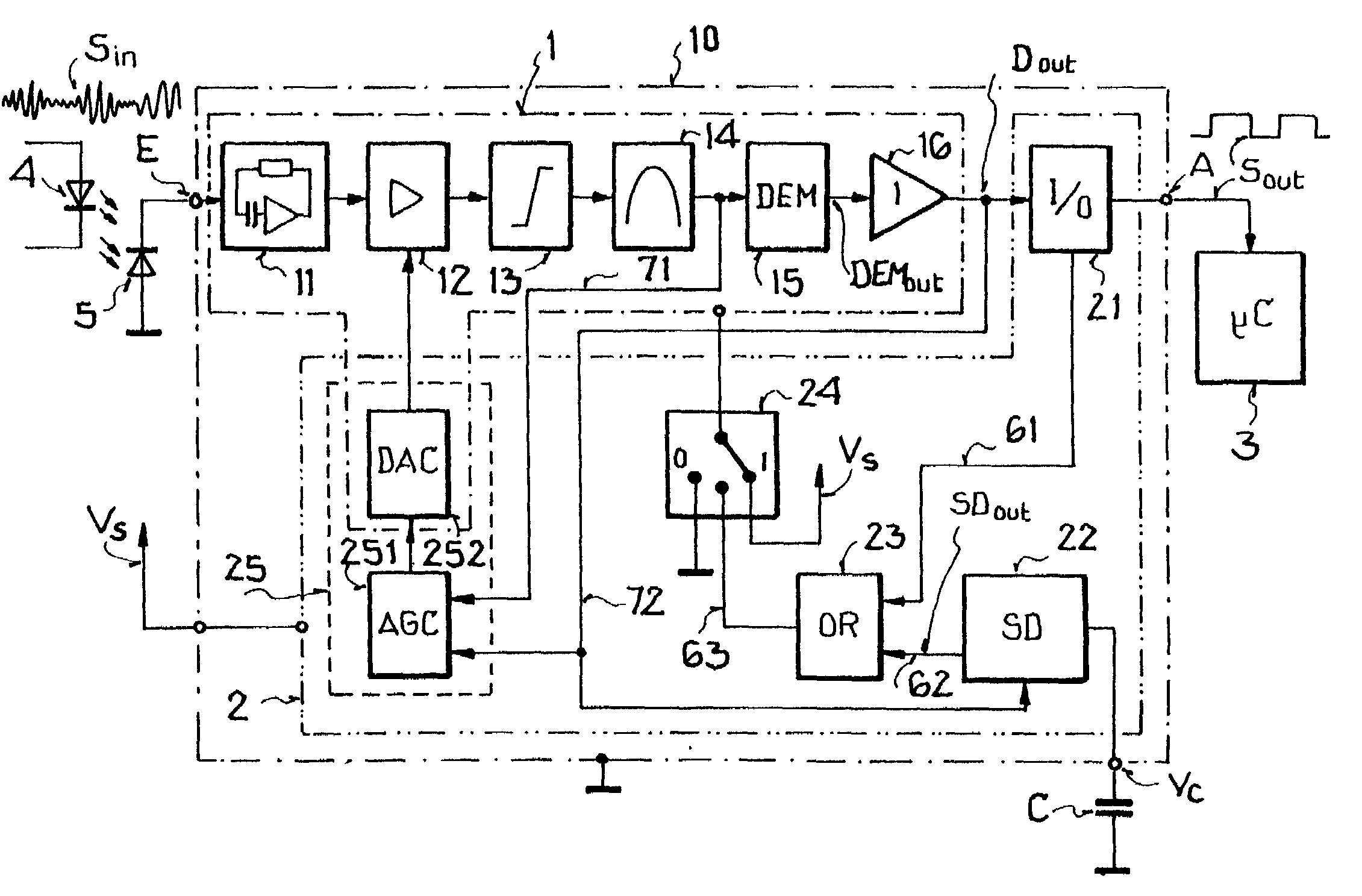
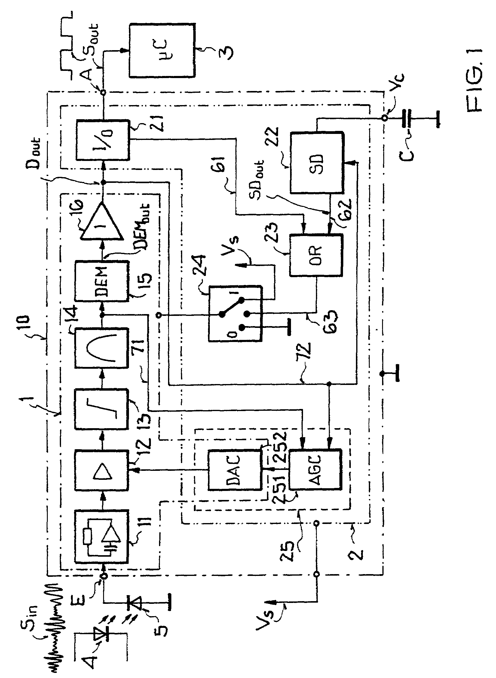
[0020]FIG. 1 shows a block diagram of a receiver circuit 10 and its environment. The carrier modulated data emitted by an optical sender diode 4 is received by a photodiode 5 as infrared pulse packets. These infrared pulse packets striking the photodiode 5 with a carrier frequency of 38 kHz for example are converted into electrical current signals SIN. They are available at the input connector E of the receiver circuit 10 These electrical current signals SIN are fed to an input circuit 11 working as a transimpedance amplifier which amplifies the current signals SIN and converts them into voltage signals. In the following signal processing component, these voltage signals are amplified by a control amplifier 12, limited by a limiter 13, and then filtered in a bandpass filter 14.

[0021]The signal limitation by means of the limiter 13 is required in order to avoid an overmodulation of the following bandpass filter 14 and to suppress pulse-shaped interference entering the receiver via a ...


PUM


Abstract

An energy-saving method for wireless reception of data modulated on a carrier signal is carried out in a receiver circuit including a first group and a second group of circuit elements. The first group of the circuit elements required for recovering the data from the modulated carrier signal are supplied intermittently with electrical energy, while the remaining circuit elements of the second group are supplied with uninterrupted electrical energy. After an intermittent unpowered phase without electrical energy being supplied to the first group of circuit elements, the receiver can be operated in the next intermittent powered phase of the second group of circuit elements with parameters that determined the receiver properties which were present in the last reception phase and that have been stored, thus eliminating the time required for renewed tuning in.

Description

BACKGROUND OF THE INVENTION[0001]The present invention relates to an energy-saving method for the wireless reception of data modulated on a carrier signal.[0002]A known, integrated receiver circuit for such an infrared remote control receiver, which has a digital gain control, is the T2521B circuit from the company ATMEL Germany GmbH. The principle of operation of such a circuit is that the carrier modulated signal—the received signal—received from a photodetector, as a rule a photodiode, is fed into an input circuit. The input circuit has a transimpedance amplifier which amplifies the pulsed input current signals and converts them into voltage signals. These voltage signals are then processed in a signal conditioning means. The signal conditioning means has a control amplifier, a limiter and a bandpass filter. In this connection, the task of the control amplifier is to amplify the output voltage from the transimpedance amplifier in accordance with the control specification. The tas...

Claims


Application Information

Patent Timeline
Patent Type & Authority Patents(United States)
IPC IPC(8): H01Q11/12H04B1/16H04B10/80
CPCH04B10/806H04B1/16
Inventor EICHIN, MATTHIASMISTELE, THOMAS
Owner VISHAY SEMICON
Why Eureka
Try Eureka