

Method for control of NOx emission from combustors using fuel dilution
- Summary
- Abstract
- Description
- Claims
- Application Information
AI Technical Summary
Benefits of technology
Problems solved by technology
Method used
Image

Examples
Embodiment Construction
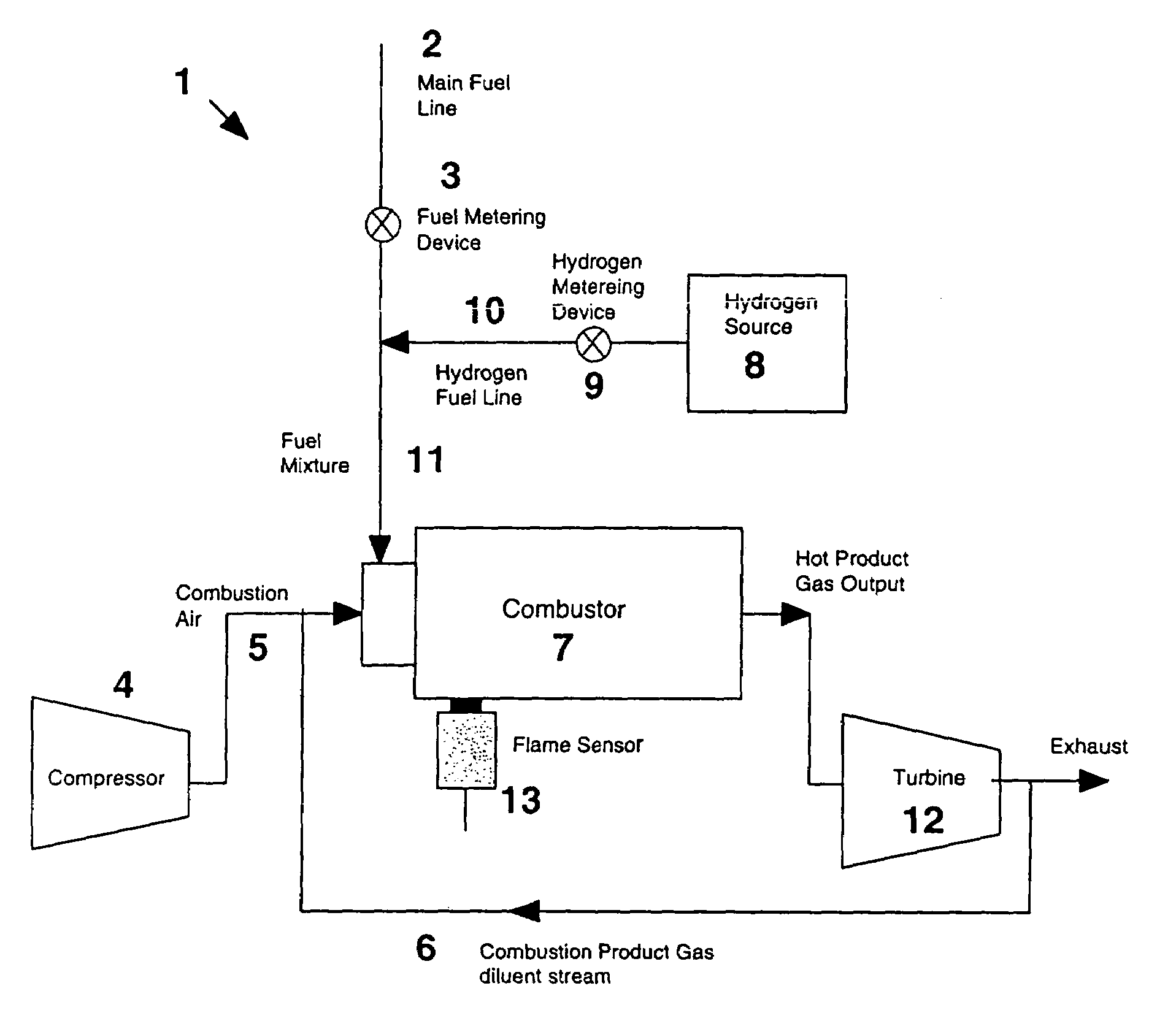
[0017]The invention is directed to a method of controlling NOx emission from combustors. The method comprises, generally, providing a inlet fuel mixture to a combustor, wherein the inlet fuel mixture comprises a base hydrocarbon fuel that can be a natural gas, methane, coal gas, biomass-derived fuel or other hydrocarbon fuel materials, a diluent gas, such as water vapor, nitrogen, or combustion product gas, and a gas capable of promoting flame stability and improve low temperature combustion characteristics, such as hydrogen.
[0018]The notation “NOx” as used herein represents all nitrogen oxides. The value of “x” can be at least one and can have non-integer values.
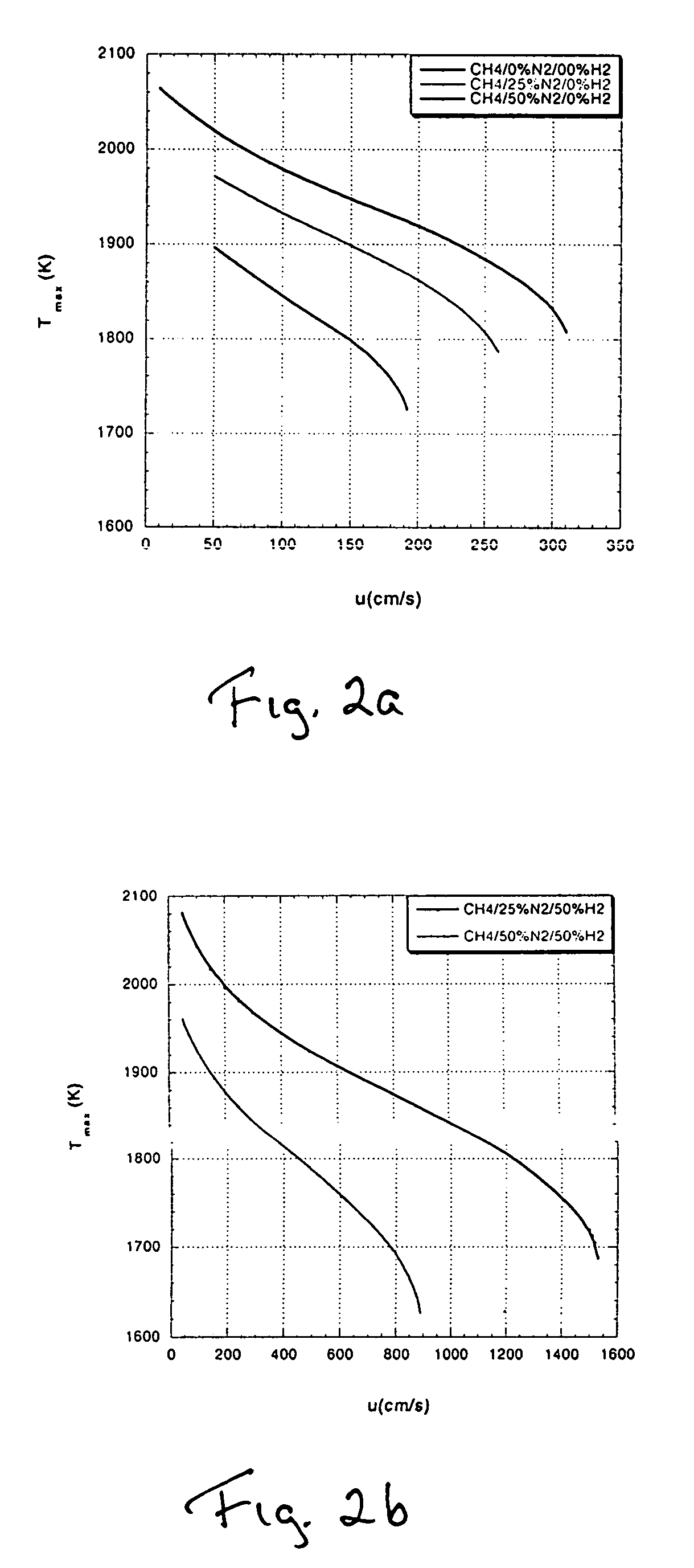
[0019]In order to demonstrate the efficacy of the invention, calculations were undertaken to demonstrate reduction in NOx emissions with diluent gas and flame stability gas additions to the inlet gas (CH4). In the cases illustrated here, the diluent gas was N2 and the gas used to provide flame stability was H2.
[0020]Calcula...
PUM
 Abstract
Description
Claims
Application Information