Power transfer system with reduced component ratings

a power transfer system and component rating technology, applied in the direction of dynamo-electric converter control, process and machine control, instruments, etc., can solve the problems of large components with appropriate ratings, short service life, and low service life of components, so as to reduce the requirement of passive components, minimize the ripple voltage of the bus, and high performance

Inactive Publication Date: 2007-01-16
INFINEON TECH AMERICAS CORP
View PDF32 Cites 57 Cited by
  • Summary
  • Abstract
  • Description
  • Claims
  • Application Information

AI Technical Summary

Benefits of technology

[0010]In accordance with the present invention, the inventors have found that the main purpose for including the passive components in the energy transfer circuits for power inverters is to absorb or deliver the difference between the instantaneous input power of the inverter and output power that is applied to a load. The output power applied to the load can be delivered to a motor or a power supply load. When the instantaneous input power tracks with the instantaneous output power, the difference between the instantaneous input power and instantaneous output power can be minimized. Accordingly, the energy to be stored or delivered by the passive component, such as a bus capacitor or DC link inductor can be minimized. For example, the DC bus ripple voltage can be minimized, as well as the DC link ripple current. By determining a particular voltage or current ripple level that can be tolerated by the specific application, the size of the DC bus capacitor or DC link inductor can be minimized accordingly.
[0011]The present invention provides a front end active control for supplying power to the DC bus connected to the power inverter. The front end active control includes a power converter with power factor correction (PFC) to make the power transfer system appear as a purely resistive load to the input power lines. The PFC power converter controls the instantaneous input power to minimize the difference between the instantaneous input power and the instantaneous output power, thereby reducing the requirements for passive components coupled to the DC bus. The instantaneous output power can be measured or calculated by obtaining values for parameters such as output current or voltage. Typically, one or more of these parameters are measured in most power transfer systems, in particular in motor drive systems, where high performance depends upon closed loop feedback with sensed parameters.
[0012]By reducing the variations in ripple current or voltage and instantaneous input and output power, the rated passive components can be specified at a much lower value, thereby providing reduced packaging size and realizing direct cost reduction.

Problems solved by technology

In addition, a dead time is provided between switching intervals when both switches in the half bridge change state.
When selecting appropriately rated passive components for use with power inverter 10, the components with appropriate ratings are typically large and somewhat expensive.

Method used


Image

  • Power transfer system with reduced component ratings
  • Power transfer system with reduced component ratings
  • Power transfer system with reduced component ratings

Examples


Embodiment Construction

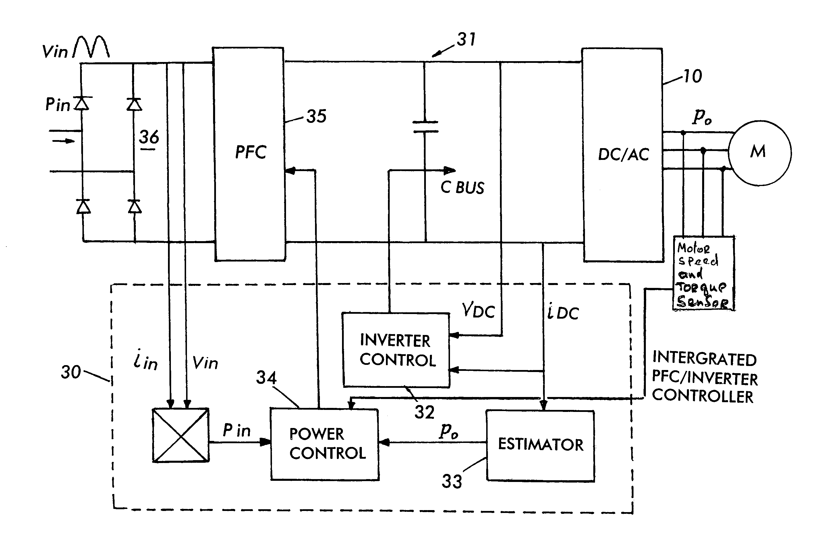
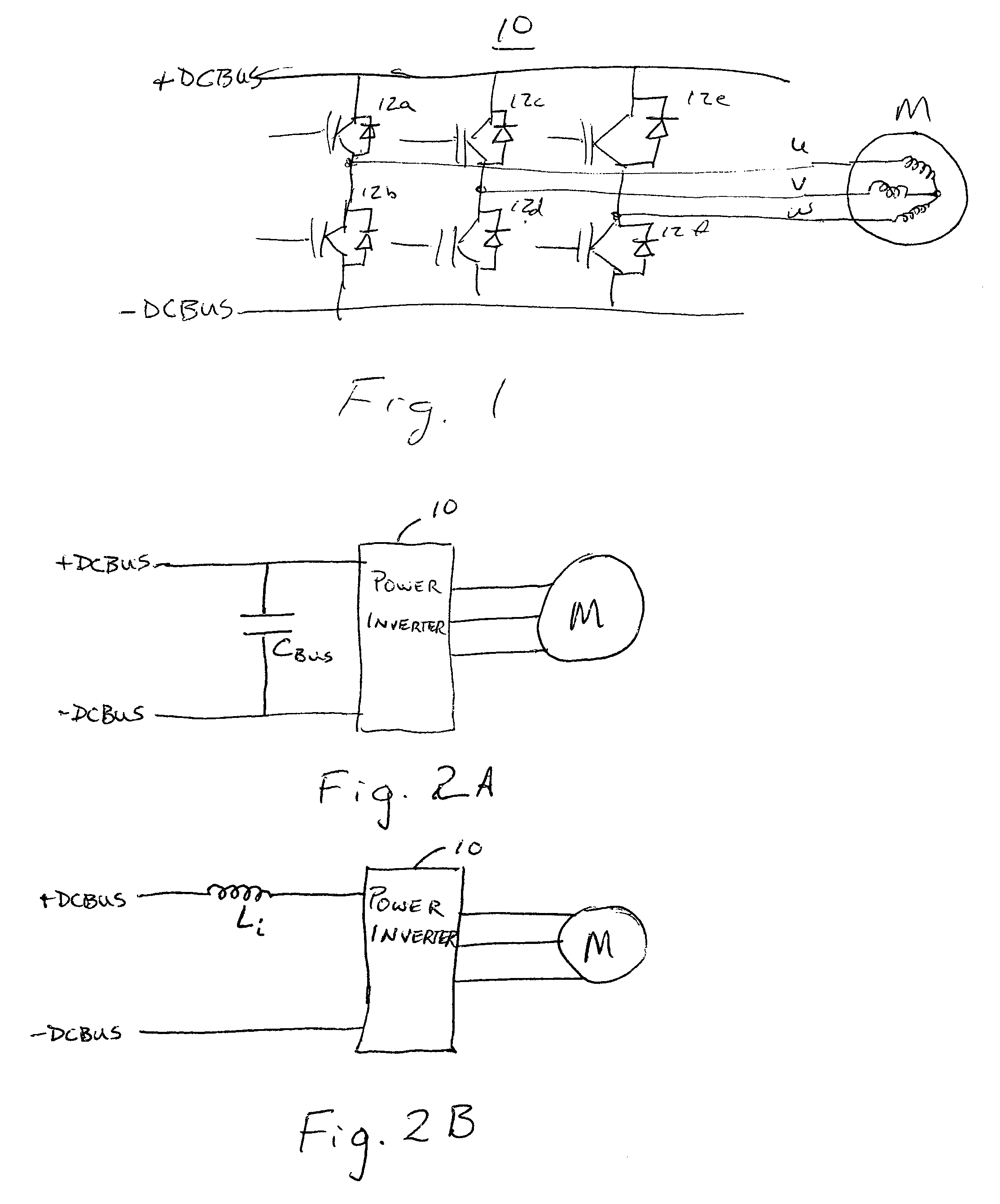
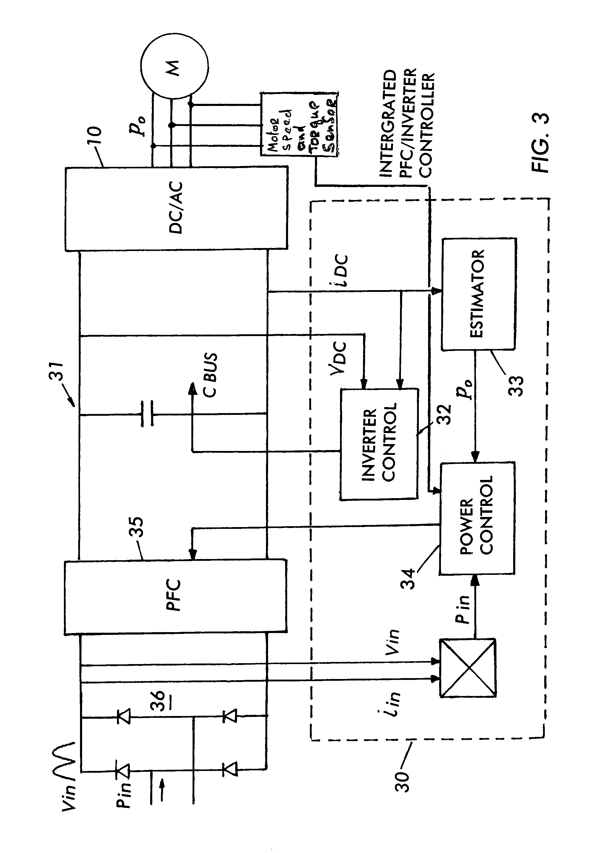
[0017]Referring now to FIG. 3, a control 30 for a motor drive system 31 is shown. Control 30 includes an inverter control 32, and estimator 33 and a power control 34. Inverter control 32 is a closed loop control for inverter 10, using as feedback signals the bus voltage VDC and the bus current IDC. Inverter control 32 provides signals for switching the power switches in inverter 10 according to an appropriate profile to obtain a desired control output for motor M. For example, motor M can be operated for torque control or velocity control based on the switching signals obtained from inverter control 32 in conjunction with the bus feedback signals VDC and IDC. Inverter control 32 can also contribute to realizing soft switching, or switching with zero current, to avoid switching losses. It should be apparent, that inverter control 32 can provide switching signals to operate inverter 10 as a single or multiple phase power supply. Power inverter 10 in motor drive system 31 is a voltage ...


PUM


Abstract

A power inverter control adjusts input power to track with output power to reduce energy handling requirements for an inverter DC bus. Input power to the power inverter circuit is measured and compared with a measurement of inverter output power. The comparison result is applied to a power factor correction circuit to adjust input power to track with output power, while obtaining a good power factor for the power inverter circuit. The energy requirements and ripple voltages or ripple currents on the DC bus are reduced, leading to a reduction in rating specifications for passive energy storage elements on the DC bus.

Description

RELATED APPLICATIONS[0001]The present application is based on and claims benefit of U.S. Provisional Application Serial No. 60 / 399,747, filed Jul. 29, 2002, entitled POWER INVERTER WITH REDUCED ENERGY CAPACITY, to which a claim of priority is hereby made.BACKGROUND OF THE INVENTION[0002]1. Field of the Invention[0003]The present invention relates generally to energy transfer devices, and relates more particularly to power inverter circuits with reduced component rating.[0004]2. Description of Related Art[0005]Typical power systems for transferring energy between an input and an output often employ a power inverter that has a DC input and a switched output that can be single or multiple phase. For example, referring to FIG. 1, an inverter for driving a three phase motor M is illustrated generally as inverter 10. Inverter 10 operates by switching the power supplied by the plus and minus DC bus lines into motor lines U, V and W to operate motor M. Switches 12a–12f are switched on and o...

Claims


Application Information

Patent Timeline
Patent Type & Authority Patents(United States)
IPC IPC(8): H02M3/335H02M7/5387H02M7/12H02P23/00
CPCH02M7/5387H02P23/0081H02P2201/15H02P23/26Y02P80/10
Inventor LI, YONGTAKAHASHI, TOSHIO
Owner INFINEON TECH AMERICAS CORP
Why Eureka
Try Eureka