Implantable stimulation device with isolating system for minimizing magnetic induction

Active Publication Date: 2007-01-16
PACESETTER INC
View PDF8 Cites 137 Cited by
  • Summary
  • Abstract
  • Description
  • Claims
  • Application Information

AI Technical Summary

Benefits of technology

[0020]Yet another feature of the present invention is to provide the attenuation system with at least a first magnetoresistor disposed in series with the feedthrough, in between the outer case and a junction along the lead. The first magnetoresistor is configured to have a relatively high resistance, and to attenuate the current induced by the external magnetic field and/or RF signals. Advantageously, the attenuation system can minimize the flow of the induction current through the induction loop, to the patient's heart, only when subjected to the external magnetic field. It is understood, however, that the flow of the induction current through the induction loop may be significantly attenuated or completely eliminated.
[0021]Still another feature of this invention is to provide a method of minimizing the flow of the induction current through the induction loop formed in the implantable device. Such a method comprises the steps of magnetically insulating at least a portion of the implantable device from the magnetic field and RF signal, and minimizing the induction current flowing through the induction loop to the patient's heart.
[0022]Another method is also provided for isolating at least one part of the device for minimizing formation of the induction loop in the implanted device through the isolated part of the implanted device. The method comprises the steps of sensing the intensity of the magnetic field and RF signa

Problems solved by technology

When the patients implanted with the devices are subjected to external electromagnetic interference, however, undesirable electric current and voltage could be induced by such interference and could create undesirable physiological effects, such as fibrillation and pain.
However, it may be unsafe and even hazardous to place patients implanted with the medical device through the MRI system because this may generate high radiofrequency (RF) signals, in the range of, for example, 64 MHz.
Such a high RF field may induce eddy currents on the conductive housing of the device, causing heat energy to be dissipated to the surrounding tissues, damaging them.
More disadvantageously, the high RF field and resulting high induced voltage may demodulate the v

Method used


Image

  • Implantable stimulation device with isolating system for minimizing magnetic induction
  • Implantable stimulation device with isolating system for minimizing magnetic induction
  • Implantable stimulation device with isolating system for minimizing magnetic induction

Examples


Example

[0036]The following description is not to be taken in a limiting sense but is made merely for the purpose of describing the general principles of the invention. In the description of the invention that follows, like numerals or reference designators will be used to refer to like parts or elements throughout. The present invention is directed at providing various magnetic field detecting isolation systems for implantable cardiac stimulating devices with pacemaking, cardioversion, and / or defibrillation capabilities, and other stimulation devices such as neurological devices.

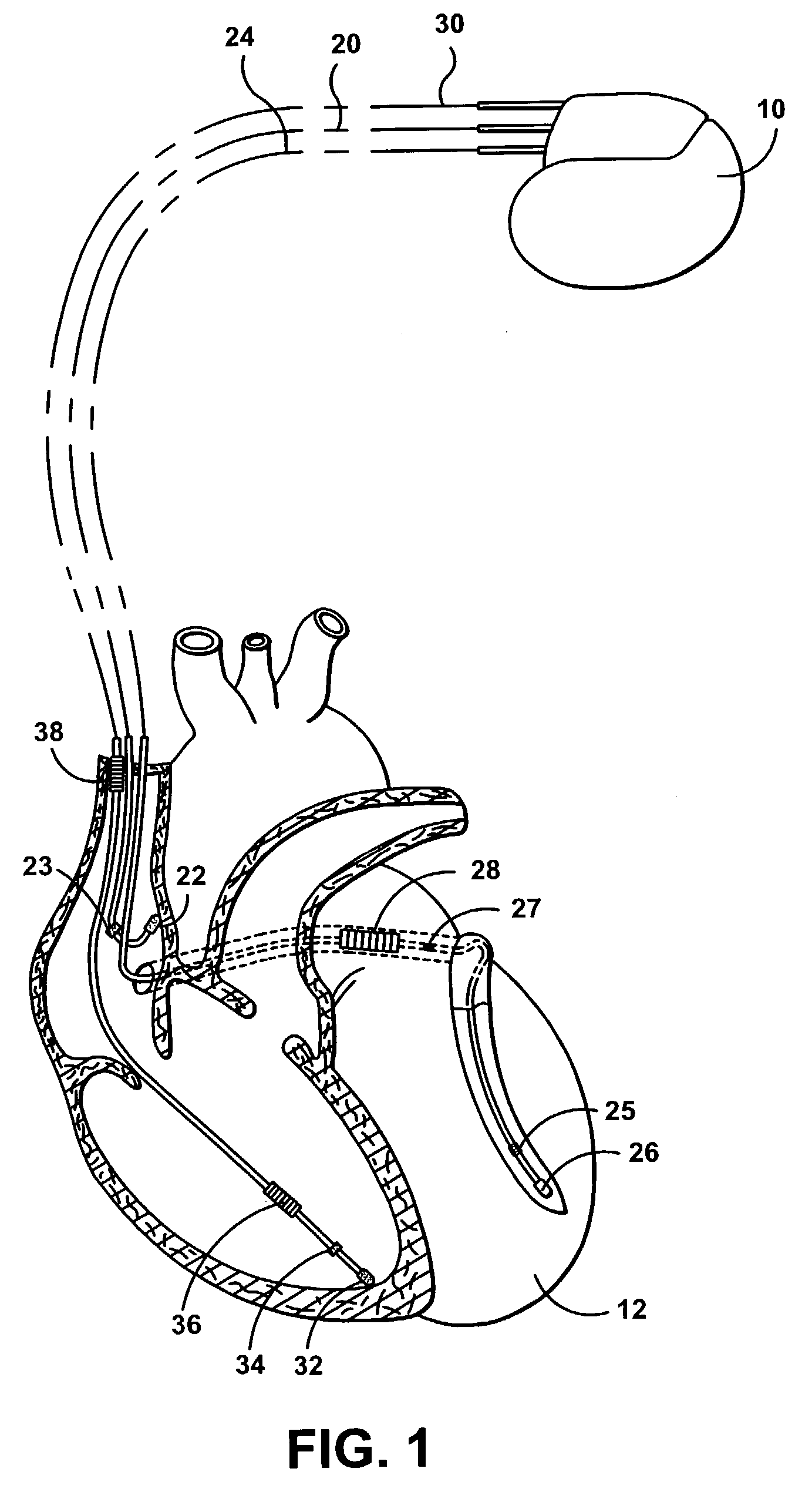
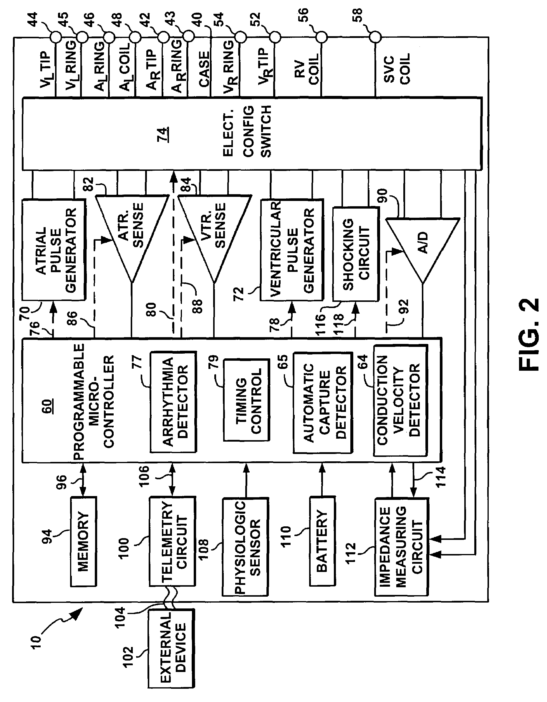
[0037]A cardiac stimulation device will thus be described in conjunction with FIGS. 1 and 2, in which the features included in this invention could be implemented. It is recognized, however, that numerous variations of such a device exist in which various methods included in the present invention can be implemented without deviating from the scope of the present invention.

[0038]FIG. 1 illustrates a stimulation devi...


PUM


Abstract

An implantable cardiac stimulation device is equipped with an isolation system capable of attenuating or eliminating induction currents flowing through the stimulation device by eliminating induction loops. The isolation system comprises a magnetic insulator configured to shield selected components of the stimulation device from external magnetic fields or radio-frequency (RF) signals. The magnetic insulator comprises a plurality of sensors that are configured to detect the intensity of the external magnetic fields and/or RF signals, and a switch bank that electrically isolates certain components of the stimulation device to eliminate the induction loops. The isolation system further comprises an attenuation system comprised of at least one magnetoresistor disposed along potential induction loops to attenuate induction currents when subjected to undesirable external magnetic fields and/or RF signals.

Description

FIELD OF THE INVENTION[0001]The present invention generally relates to implantable cardiac stimulation devices. More specifically, the present invention relates to implantable cardioverter defibrillators that are equipped with insulation, isolation, and / or attenuation systems capable of minimizing induction currents flowing through the implantable devices, or eliminating induction loops through which the induced electric current flows.BACKGROUND OF THE INVENTION[0002]Implantable medical devices have been developed to support various body functions internally without having to connect wires through the skin. Examples of these devices include implantable pacemakers, cardioverters or defibrillators for monitoring and for stimulating ailing hearts. Implantable bladder stimulators provide electrical stimuli to bladder muscles to restore bladder function. Similar types of electrical stimuli provided by bone growth stimulators help the patients with complicated bone fractures. Cerebellar i...

Claims


Application Information

Patent Timeline
IPC IPC(8): A61N1/372A61N1/368A61N1/37
CPCA61N1/368A61N1/37A61N1/3718
Inventor KROLL, MARK W.SALYS, SCOTTCOX, TIMOTHY J.SCHIMKE, KERWYN
Owner PACESETTER INC
Why Eureka
Try Eureka