Wave gear device having internal gear integrally formed with inner ring of bearing

a gear device and wave technology, applied in the direction of gearing, bearing unit rigid support, hoisting equipment, etc., can solve the problems of occasionally impossible to ensure moment rigidity and permissible moment load, and achieve the effect of reducing size and weight of the apparatus, high abrasive resistance, and good precision

Active Publication Date: 2007-01-23
HARMONIC DRIVE SYST IND CO LTD
View PDF6 Cites 15 Cited by
  • Summary
  • Abstract
  • Description
  • Claims
  • Application Information

AI Technical Summary

Benefits of technology

[0005]In view of the above, a main object of the present invention is to provide a wave gear device having an internal gear integrally formed with an inner ring of a bearing that has high machining precision and abrasion resistance of internal teeth, as well as high device rigidity and permissible moment load.
[0018]In the wave gear device in accordance with the present invention as described above, the composite member that functions as the inner ring of the bearing and the internal gear has a configuration in which the internal teeth-forming member composed of a ductile casting is integrated by diffusion bonding with the inner ring-forming member composed of bearing steel. Accordingly, the size and weight of the apparatus can be reduced in a manner similar to the case in which an inner ring portion and an internal teeth portion are formed in a single member. At the same time, internal teeth that have good precision and high abrasive resistance can be formed, and the rigidity of the device and the permissible moment load can be increased.

Problems solved by technology

However, when a wave gear device is manufactured using a single member composed of a ductile casting in which an inner ring raceway surface and internal teeth are formed, it is occasionally impossible to ensure moment rigidity and a permissible moment load.

Method used


Image

  • Wave gear device having internal gear integrally formed with inner ring of bearing
  • Wave gear device having internal gear integrally formed with inner ring of bearing
  • Wave gear device having internal gear integrally formed with inner ring of bearing

Examples


Embodiment Construction

[0023]Embodiments of the wave gear device according to the present invention are described hereinbelow with reference to the diagrams.

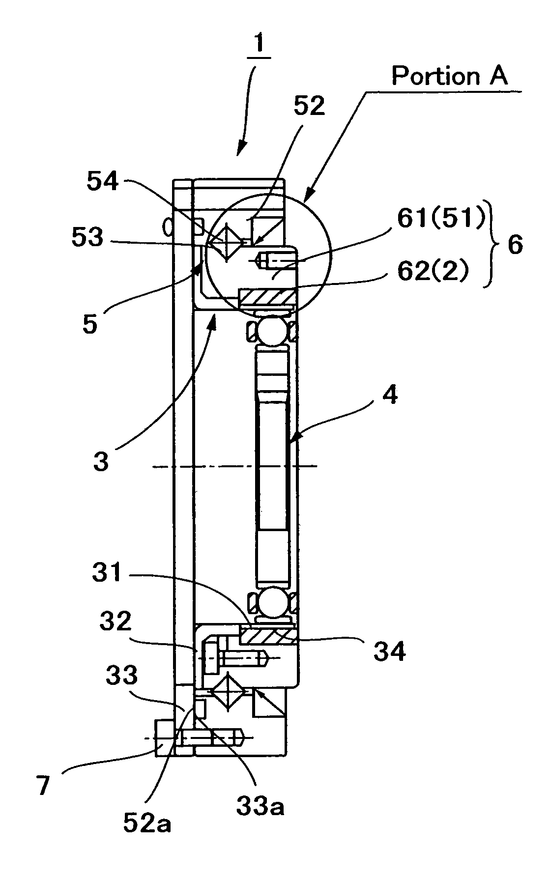
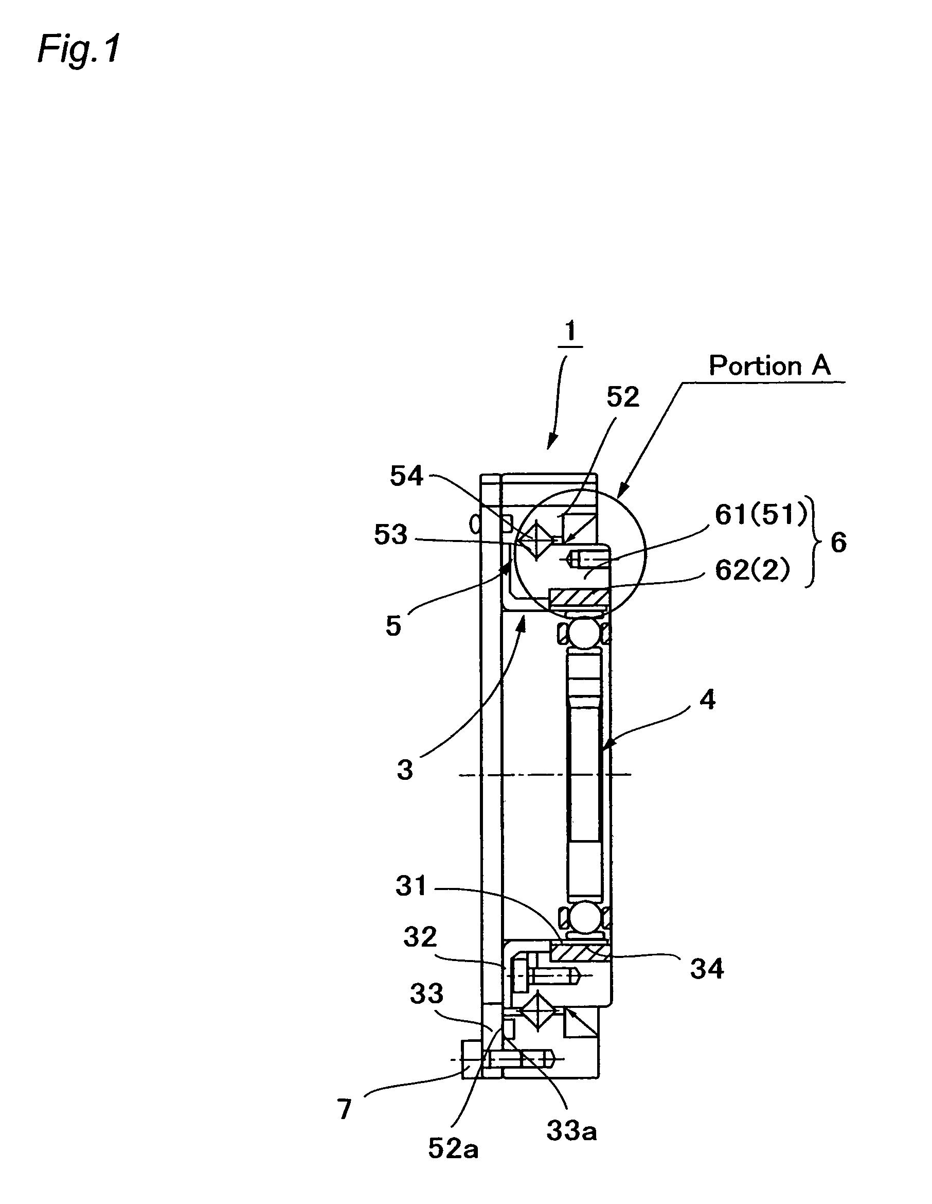
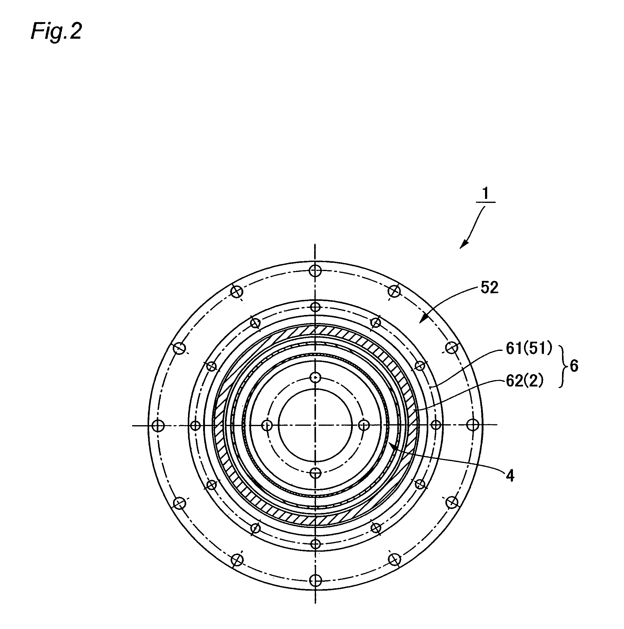
[0024]FIGS. 1, 2, and 3 are a cross-sectional view, a right side end face view, and a left side end face view of a silk hat-type wave gear device of the present invention. FIG. 4 is a partial enlarged cross-sectional view thereof. The wave gear device 1 has an annular rigid internal gear 2, a silk hat-shaped flexible external gear 3 disposed coaxially inside the rigid internal gear, an elliptically contoured wave generator 4 fitted into the flexible external gear, and a cross roller bearing 5 for supporting the rigid internal gear 2 and the flexible external gear 3 in a relatively rotatable manner.

[0025]The silk hat-shaped flexible external gear 3 has a cylindrical trunk 31, an annular diaphragm 32 that widens radially outward from one end of the trunk 31, an annular boss 33 formed in a continuous fashion on an outer peripheral edge of the diaphragm 3...


PUM


Abstract

A wave gear device has a rigid internal gear, a flexible external gear, a wave generator, and a cross roller bearing for supporting the gears in a relatively rotatable manner. A toroidal composite member that functions as the rigid internal gear and an inner ring of the cross roller bearing has an inner ring-forming member that functions as the inner ring, and an internal teeth-forming member that functions as the rigid internal gear, and the internal teeth-forming member composed of a ductile casting is integrated by diffusion bonding with the inner ring-forming member composed of bearing steel.

Description

FIELD OF THE INVENTION[0001]The present invention relates to a wave gear device configured so as to generate relative rotation between a flexible external gear and an annular rigid internal gear by causing the flexible external gear to partially mesh with the annular rigid internal gear, and circumferentially moving meshing positions of the gears; and particularly relates to a wave gear device with a configuration in which the internal gear is integrated with an inner ring of a bearing that supports the gears in a relatively rotatable manner.DESCRIPTION OF THE RELATED ART[0002]Commonly known wave gear devices have an annular rigid internal gear, a flexible external gear disposed inside thereof, and an elliptically contoured wave generator. The flexible external gear is elliptically flexed by the wave generator so as to partially mesh with the rigid internal gear. When the wave generator is rotated by a motor or the like, meshing locations of the two gears move circumferentially. Sin...

Claims


Application Information

Patent Timeline
Patent Type & Authority Patents(United States)
IPC IPC(8): F16H33/00F16C35/06F16C19/36F16H1/32F16H49/00F16H55/08
CPCF16H49/001Y10T74/19F16C19/362F16C33/581
Inventor KOBAYASHI, MASARUKUROGI, JUNICHI
Owner HARMONIC DRIVE SYST IND CO LTD
Why Eureka
Try Eureka