
Measuring method of spatially resolved frequency selective images

a spatial resolution and selective image technology, applied in the field of spatial resolution spectroscopic recordings, can solve the problem of time-consuming and laborious measurement schemes

Inactive Publication Date: 2007-01-23
UNIV ZURICH +1
View PDF3 Cites 3 Cited by
  • Summary
  • Abstract
  • Description
  • Claims
  • Application Information

AI Technical Summary

Benefits of technology

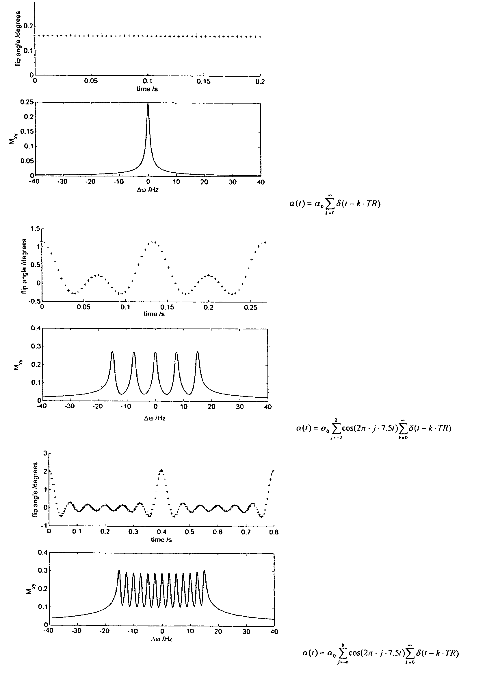
[0020]A particularly preferred version of the above is when the N excitations all have the same excitation level and a set of equidistant frequencies are superposed to create selective images from a band of frequencies. Frequencies outside of this band will be suppressed and the excitation of only a band of frequencies facilitates a more rapid measurement as fewer signals need to be recombined to reconstruct the spectrally selective image at a given spectral resolution. The single resonances then can be separated by a discrete Fourier transform.
[0021]In a further preferred variant, switching of a magnetic gradient field spatially limits the excitation volume simultaneously with irradiation of the exciting RF pulses. This facilitates precise limitation of the NMR measurement to certain parts of the measuring object thereby.
[0022]In a further preferred variant the action integral over the gradient between excitations is not zero, but a constant value per time between two excitations. Thereby a frequency axis is mapped onto the direction of the integral over the gradient and the resonances will occur in both the frequency and the spatial dimension. Repeating the experiment with different gradient per time unit remainder allows for spatial encoding and generation of images thereby.

Problems solved by technology

Accordingly, these measuring schemes are time inefficient.
One practical drawback when applying short TR sequences relates to power deposition in the object, which is of particular relevance in the in-vivo application.

Method used


Image

  • Measuring method of spatially resolved frequency selective images
  • Measuring method of spatially resolved frequency selective images
  • Measuring method of spatially resolved frequency selective images

Examples


Embodiment Construction

[0060]The exemplifications set out herein are not to be construed as limiting the scope of this disclosure or the scope of this invention in any manner.

[0061]The nuclear magnetic resonance imaging system shown in FIG. 2 includes a set of main coils 10 whereby a steady, spatially uniform magnetic field is generated. The main coils are constructed, for example, in such a manner that they enclose a tunnel-shaped examination space. A patient to be examined is slid on a table into this tunnel-shaped examination space.

[0062]The magnetic resonance imaging system also includes a number of gradient coils 12, whereby magnetic fields exhibiting spatial variations, notably in the form of temporary gradients in individual directions, are generated so as to be superposed on the uniform magnetic field. The gradient coils 12 are connected to a controllable power supply unit 21. The gradient coils 12 are energized by application of an electric current by means of the power supply unit 21. The streng...


PUM


Abstract

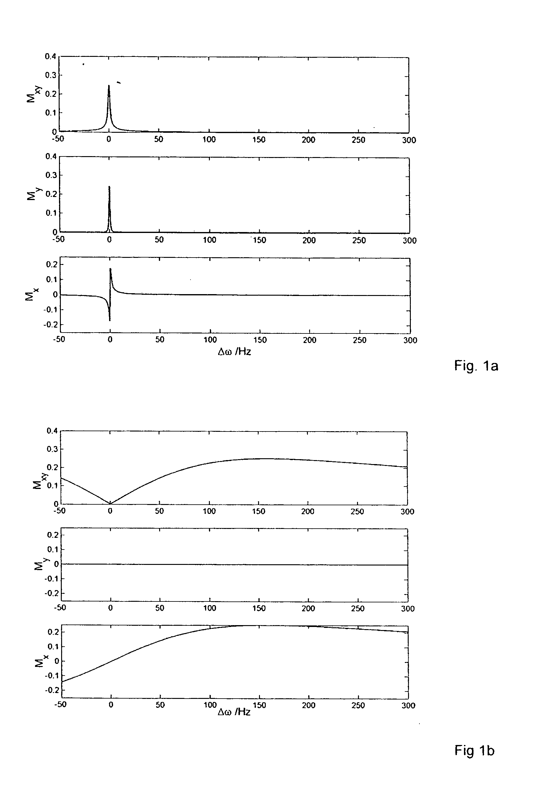
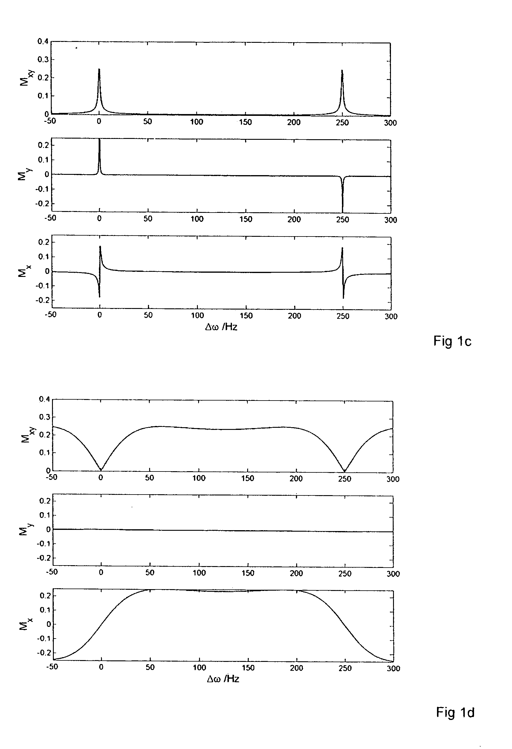
The present invention describes a magnetic resonance imaging method wherein spatially resolved frequency sensitive image data are collected by means of free precession sequences employing very small radio frequency (RF) excitation pulses per unit time which result in highly frequency selective steady-state signals dominated by linear properties of the system, for which the superposition principle holds. By appropriate linear combination of steady state signals of N different frequencies, N resonance lines can be acquired simultaneously. This method allows spectroscopic recordings with very low RF power deposition which renders the method suitable for applications at high static magnetic field strengths.

Description

BACKGROUND OF THE INVENTION[0001]The invention relates to spatially resolved spectroscopic recordings using nuclear magnetic resonance (NMR) methods. Such methods are known as chemical shift imaging (CSI) wherein nuclear spins are excited by means of radio frequency (RF) pulses and a signal thereof is recorded after a certain time during which spatial encoding of the signal by means of a gradient pulse in at least one spatial direction is imposed, wherein said gradient pulse is varied successively from one recording step to the next to encode spatial position of multiple measuring volumes. A method of this type is known e.g. from the publication by T. R. Brown et al. “NMR chemical shift imaging in three dimensions”, Proc. Natl. Acad. Sci. USA, Vol. 79, 3523–3526 (1982).[0002]In aforementioned method, excitation steps are repeated at a repetition time interval TR, wherein TR is typically chosen to be in the order of the longitudinal relaxation time T1, which is much longer than the t...

Claims


Application Information

Patent Timeline
Patent Type & Authority Patents(United States)
IPC IPC(8): G01V3/00G01R33/483G01R33/561
CPCG01R33/4833G01R33/5613
Inventor EBERHARDT, KAISCHAR, MICHAELBARMET, CHRISTOPHBOESIGER, PETERKOZERKE, SEBASTIAN
Owner UNIV ZURICH
Learn More