System and method for reducing fiber optic gyroscope color noise

a fiber optic gyroscope and color noise technology, applied in the field of control of fiber optic gyroscopes, can solve the problems of reducing the stability of the system at or near zero input rate, and affecting the accuracy of the measurement. , to achieve the effect of eliminating the rds and suppressing the color nois

Inactive Publication Date: 2007-01-23
HONEYWELL INT INC
View PDF6 Cites 14 Cited by
  • Summary
  • Abstract
  • Description
  • Claims
  • Application Information

AI Technical Summary

Benefits of technology

[0013]According to the preferred exemplary embodiments of the present invention, there is provided a phase jump amplitude and timing controller for suppressing color noise due to the repeated drive signal to phase modulator. The phase jump amplitude and timing controller inserts a phase/voltage jump into the feedback signal of the loop closure electronics of the fiber optic gyroscope. This phase/voltage jump breaks the repeated pattern of the drive signal. The IOC time-dependent characteristics are totally eliminated by the randomized feedback signal because n

Problems solved by technology

After traversing the loop, the counter-propagating waves are combined so that they constructively or destructively interfere to form an optical output signal.
However, certain voltage-dependent errors in the feedback signal, phase servo, or electrical cross-coupling, can all cause the servo loop to become less stable at certain rotation rates.
In particular,

Method used


Image

  • System and method for reducing fiber optic gyroscope color noise
  • System and method for reducing fiber optic gyroscope color noise
  • System and method for reducing fiber optic gyroscope color noise

Examples


Embodiment Construction

[0021]The following detailed description of a preferred embodiment is merely exemplary in nature and is not intended to limit the invention or the application and uses of the invention.

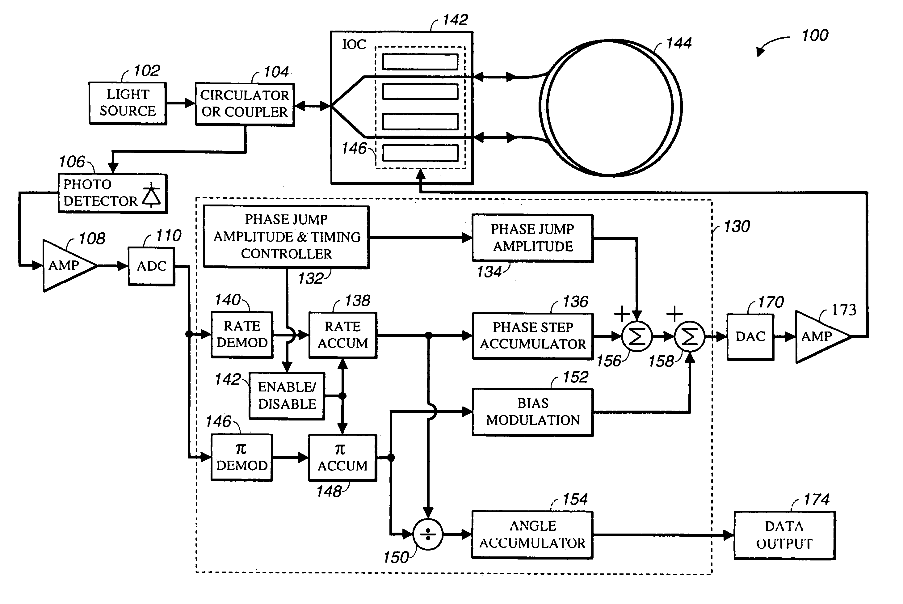
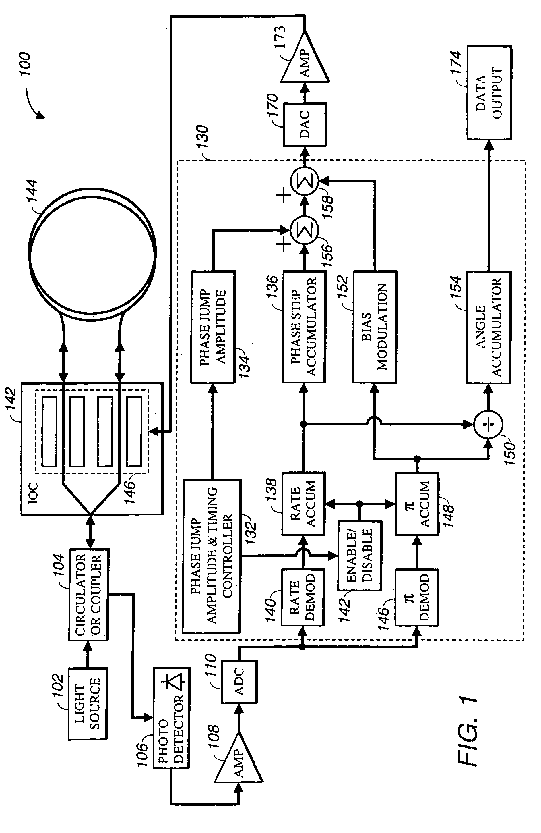
[0022]Referring now to FIG. 1, a fiber optic gyroscope 100 with a preferred exemplary embodiment of color noise suppression loop closure electronics comprises: a light source 102; a circulator / coupler 104; an Integrated Optics Chip (IOC) 142; a fiber coil 144; a photo detector 106; an amplifier 108, an analog-to-digital converter 110; a color noise suppression module 130; a DAC 170; an amplifier 173; and a data output point 174.

[0023]Light source 102 is any typical fiber light source used by those skilled in the art to manufacture fiber optic gyroscopes. The most preferred embodiment of light source 102 is a 980 nm semiconductor pump laser containing an erbium fiber and fiber bragg gratings capable of shaping the output wavelength to approximately 1,532 nm with an approximate bandwidth of 8 nm. The se...


PUM


Abstract

A phase jump amplitude and timing controller is used in a fiber optic gyroscope for suppressing color noise. The phase jump amplitude and timing controller inserts a phase/voltage jump into the feedback signal of the loop closure electronics of the fiber optic gyroscope. This phase/voltage jump breaks the repeated pattern of the drive signal. The IOC time-dependent characteristics are totally eliminated by the randomized feedback signal because no repeated signal is applied to the IOC. The randomized amplitude is preferably within the full ±π phase such that the optical errors average to zero. A fixed frequency higher than the interested spectral region can shift the color noise to higher frequency. A randomized frequency can spread the color noise over full spectrum, and totally eliminate the RDS. In other words, the color noise caused by the nonlinearity of the driving circuit and IOC spreads out over a wide range of spectrum such that no distinct frequency peaks are apparent in the spectral domain.

Description

[0001]This application is a continuation-in-part of U.S. patent application Ser. No. 10 / 135,245, filed Apr. 30, 2002, now U.S. Pat. No. 6,744,519, which is herein incorporated by reference in its entirety.BACKGROUND[0002]1. Field of the Invention[0003]The present invention relates generally to the control of fiber optic gyroscopes, and more particularly to a method and apparatus to suppress color noise in fiber optic gyroscopes.[0004]2. Background of the Invention[0005]Inertial rotation sensors, for determining orientation and / or rate-of-turn with respect to an inertial frame of reference, are important elements of attitude and heading reference systems used by navigable vehicles such as aircraft. For a long period of time, such orientation and rate-of-turn determinations have typically been made using spinning mass gyroscopes. Progress in the field has resulted in many refinements and the development of various types of gyroscopes suited to specific applications. In recent years, f...

Claims


Application Information

Patent Timeline
IPC IPC(8): G01C19/72
CPCG01C19/726
Inventor CHEN, CHUNG-JENLANGE, CHARLES H.
Owner HONEYWELL INT INC
Why Eureka
Try Eureka