Electrode and electrochemical cell therewith

a technology applied in the field of electrochemical cells and electrodes therewith, can solve the problems of reducing the electrochemical reaction speed, reducing the electrode resistance, so as to improve the electron conductivity, the effect of good cycle properties and electrode strength, and quick charge/discharg

Inactive Publication Date: 2007-01-30
TOKIN CORP
View PDF8 Cites 14 Cited by
  • Summary
  • Abstract
  • Description
  • Claims
  • Application Information

AI Technical Summary

Benefits of technology

[0026]This invention can provide an electrochemical cell capable of quick charge / discharge and exhibiting good cycle properties and electrode strength because an electrode having improved electron conductivity and a lower resistivity can be provided by filling pores in a porous conductive substrate as a support with an electrode material, because an electrode exhibiting good shape stability (strength) can be provided by using a support consisting of a porous conductive substrate and because by using a porous conductive substrate, the amount of an electrolytic solution impregnated can be increased to improve ion conductivity within the electrode.
[0027]This invention can also provide an electrode exhibiting improved shape stability (strength), a lower resistivity and better response than an electrode according to the prior art. Furthermore, a thickness of the porous conductive substrate as a support can be selected such that an electrode having an appropriate film thickness can be readily prepared; in particular, an electrode can be easily made thinner, an electrode resistivity can be reduced and an electrochemical cell can be readily made thinner.

Problems solved by technology

In the conventional method (1) for forming an electrode, preparation of a thinner electrode is difficult, an electrode resistivity is higher due to limitations in its shape, an electrochemical reaction is slower and the electrode exhibits poor quick charge-discharge behavior.
In the conventional method (2) for forming an electrode, preparation of a slurry giving desired properties or selection of a binder is difficult and a manufacturing process becomes more complex for preparing an electrode with good properties.
Furthermore, an electrode prepared from the above slurry has a problem that breaks, cracks or detachment may occur during drying or impregnation of an electrolytic solution, leading to poor adhesiveness to a current collector and an increased contact resistance or an electrode resistance.
The electrode also has a problem that in both conventional methods (1) and (2) for forming an electrode, expansion associated with an electrochemical reaction of a proton-conducting compound with a dopant and swelling due to impregnation of an electrolytic solution cause reduction in electrode strength and breaks and cracks, leading to an increased internal resistance and deteriorated cycle properties.
However, it leads to a complex manufacturing process and an increased production cost.
As described above, the first problem in a conventional process for forming an electrode is that since a thinner electrode cannot be formed by an electrode-forming process employing press molding, an electrode resistivity is increased, leading to deteriorated response in an electrochemical reaction.
The second problem is that since adhesiveness between an electrode and a current collector is inadequate or an electrode itself has poor strength according to the electrode-forming process employing a coating by screen-printing, a film electrode exhibiting good properties cannot be prepared.
Furthermore, the third problem is that an electrode exhibits poor shape stability, i.e., strength during production or an electrochemical reaction.

Method used


Image

  • Electrode and electrochemical cell therewith
  • Electrode and electrochemical cell therewith
  • Electrode and electrochemical cell therewith

Examples


example 1

[0077]A cathode active material was 5-cyanoindole trimer compound as a proton-conducting compound, a cathode conductive auxiliary was fibrous carbon (VGCF); and a binder was PVDF with an average molecular weight of 1,100. These were sequentially weighed to a weight ratio of 69 / 23 / 8 and mixed by stirring in a blender.

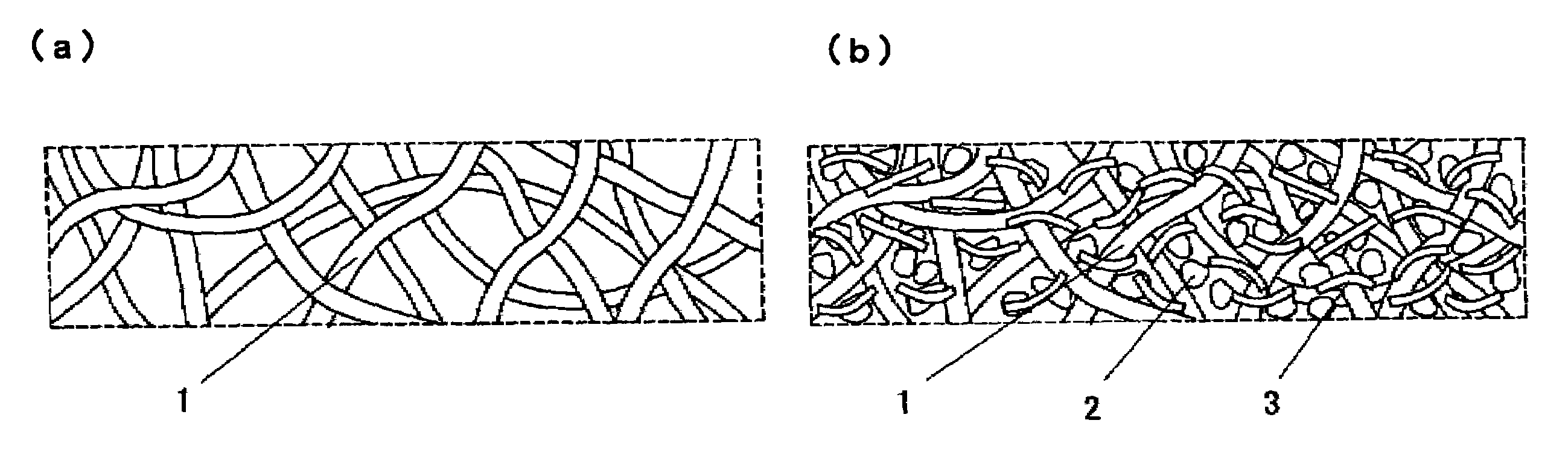
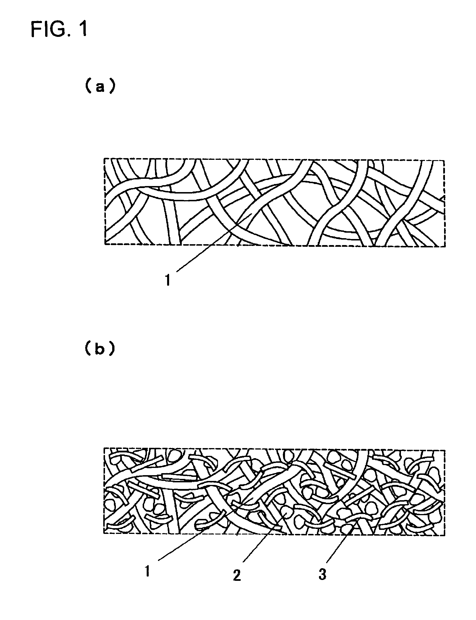
[0078]Then, 10 mg of the mixture powder was stirred in 1 mL of DMF for 5 min at an ambient temperature to give a homogeneously dispersed slurry. A porous conductive substrate as a support for an electrode was a non-woven carbon-fiber fabric with a porosity of 45% and a thickness of 80 μm. Pores in the porous conductive substrate were filled with the resulting slurry using a squeegee to give a cathode with a filling rate of 12% and a thickness of 100 μm, which was then cut into a predetermined shape for use.

[0079]Then, polyphenylquinoxaline, a proton-conducting polymer, was used as an anode active material and Ketjen Black (Ketjen Black International Company, EC-600JD) wa...

example 2

[0083]An electrochemical cell for a secondary battery was prepared as described in Example 1, except that a non-woven carbon fiber fabric with a porosity of 78% and a thickness of 80 μm was used as a porous conductive substrate for a support in an electrode. The resulting cathode had a filling rate of 20% and a thickness of 100 μm while the anode had a filling rate of 20% and a thickness of 100 μm.

example 3

[0084]As described in Example 2, a non-woven carbon fiber fabric with a porosity of 78% and a thickness of 80 μm was used as a porous conductive substrate for a support in an electrode. A slurry prepared as described in Example 1 was used in impregnation under a pressure to give a cathode with a filling rate of 30% and a thickness of 100 μm. Similarly, an anode with a filling rate of 30% and a thickness of 100 μm was prepared. As described in Example 1 for the other conditions, an electrochemical cell for a secondary battery was prepared.


PUM

PropertyMeasurementUnit
porosityaaaaaaaaaa
lengthaaaaaaaaaa
diameteraaaaaaaaaa

Abstract

This invention provides an electrode comprising a porous conductive substrate as well as an electrode active material and a conductive auxiliary filled in the pores in the substrate. This electrode exhibits improved shape stability (strength), a lower resistivity and better response. This electrode can be used to provide an electrochemical cell capable of quick charge/discharge and exhibiting improved cycle properties.

Description

BACKGROUND OF THE INVENTION[0001]1. Field of the Invention[0002]This invention relates to an electrode comprising a support for improving strength and conductivity and an electrochemical cell therewith such as a secondary battery and an electric double-layer capacitor.[0003]2. Description of the Related Art[0004]There have been suggested and practically used electrochemical cells such as secondary batteries and capacitors in which a proton-conducting polymer is used as an electrode active material. FIG. 4 shows a cross section of a conventional electrochemical cell.[0005]As shown in FIG. 4, the conventional electrochemical cell has a configuration where a cathode 6 and an anode 7 containing a proton-conducting polymer as an active material are formed on a cathodic current collector 4 and an anodic current collector 5, respectively, these electrodes are combined via a separator 8 and only protons are involved as a charge carrier. The cell is filled with an aqueous or non-aqueous solu...

Claims


Application Information

Patent Timeline
Patent Type & Authority Patents(United States)
IPC IPC(8): H01M4/58H01M4/60H01M4/80H01M4/02H01G9/04H01G9/145H01G9/22H01G11/02H01G11/26H01G11/40H01G11/62H01M4/04H01M4/62H01M4/86H01M4/90H01M4/96
CPCH01G9/058H01G9/155H01G9/22H01G11/02H01G11/26H01G11/62H01M4/0404H01M4/60H01M4/602H01G11/40Y02E60/13Y02E60/10H01G11/28H01G11/48H01G11/70B42D15/0053B42D25/27G09F23/10H01G11/22
Inventor NOBUTA, TOMOKIKAMISUKI, HIROYUKIMITANI, MASAYAKANEKO, SHINAKOYOSHINARI, TETSUYA
Owner TOKIN CORP
Why Eureka
Try Eureka