Laser etching method and apparatus therefor

a laser etching and laser etching technology, applied in the field of laser etching methods and laser etching apparatuses, can solve the problems of increased cost and hardly applicable laser working methods to the formation of articles

Inactive Publication Date: 2007-01-30
CANON KK
View PDF30 Cites 26 Cited by
  • Summary
  • Abstract
  • Description
  • Claims
  • Application Information

AI Technical Summary

Benefits of technology

[0013]wherein, in laser etching of the work article formed of the inorganic material by irradiation thereof with the laser light from the laser oscillator with a predetermined pattern and with a predetermined energy density, there is utilized means for preventing deposition of a work by-product around the etching position.
[0033]means for preventing deposition of a work by-product around the etching position for laser etching by irradiation of the work article formed of the inorganic material.

Problems solved by technology

However, as the energy density of the laser light in the oscillated pulse is limited to a level of 100 megawatts at maximum, such laser working method is hardly applicable to an article formed of an inorganic material and is only applicable to the sublimation ablation working of articles principally composed of organic materials.
For this reason, the fine working of the article formed of inorganic materials has been achieved by a lithographic process including steps of resist coating, resist patterning by exposure, resist development, etching utilizing the resist pattern and resist ashing for each material, but such process is associated with drawbacks of an increased cost resulting from the complex process steps and a large investment for the production facility in consideration of the process tact time.

Method used


Image

  • Laser etching method and apparatus therefor
  • Laser etching method and apparatus therefor
  • Laser etching method and apparatus therefor

Examples


embodiment 1

[Embodiment 1]

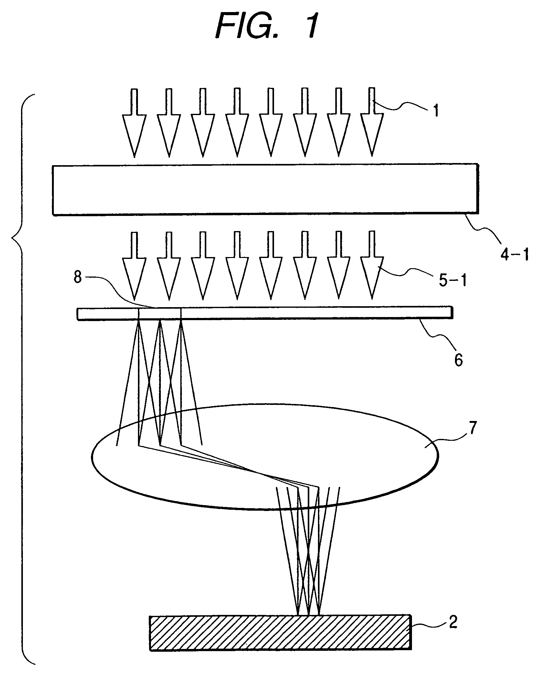
[0071]At first reference is made to FIG. 1 for outlining the working method of an embodiment 1 of the present invention. A laser light 1, emitted from an unrepresented laser oscillator, capable of emitting the laser light with an extremely short pulse emission time (not exceeding 1 picosecond), after being modulated by a mechanical shutter 4-1 into a pulse train 5-1 of laser light cut in time, illuminates a photomask 6, and the light transmitted by a mask pattern 8 is projected and focused through a projection lens 7. The projected image is focused on the surface of a work article 2 formed of an inorganic material.

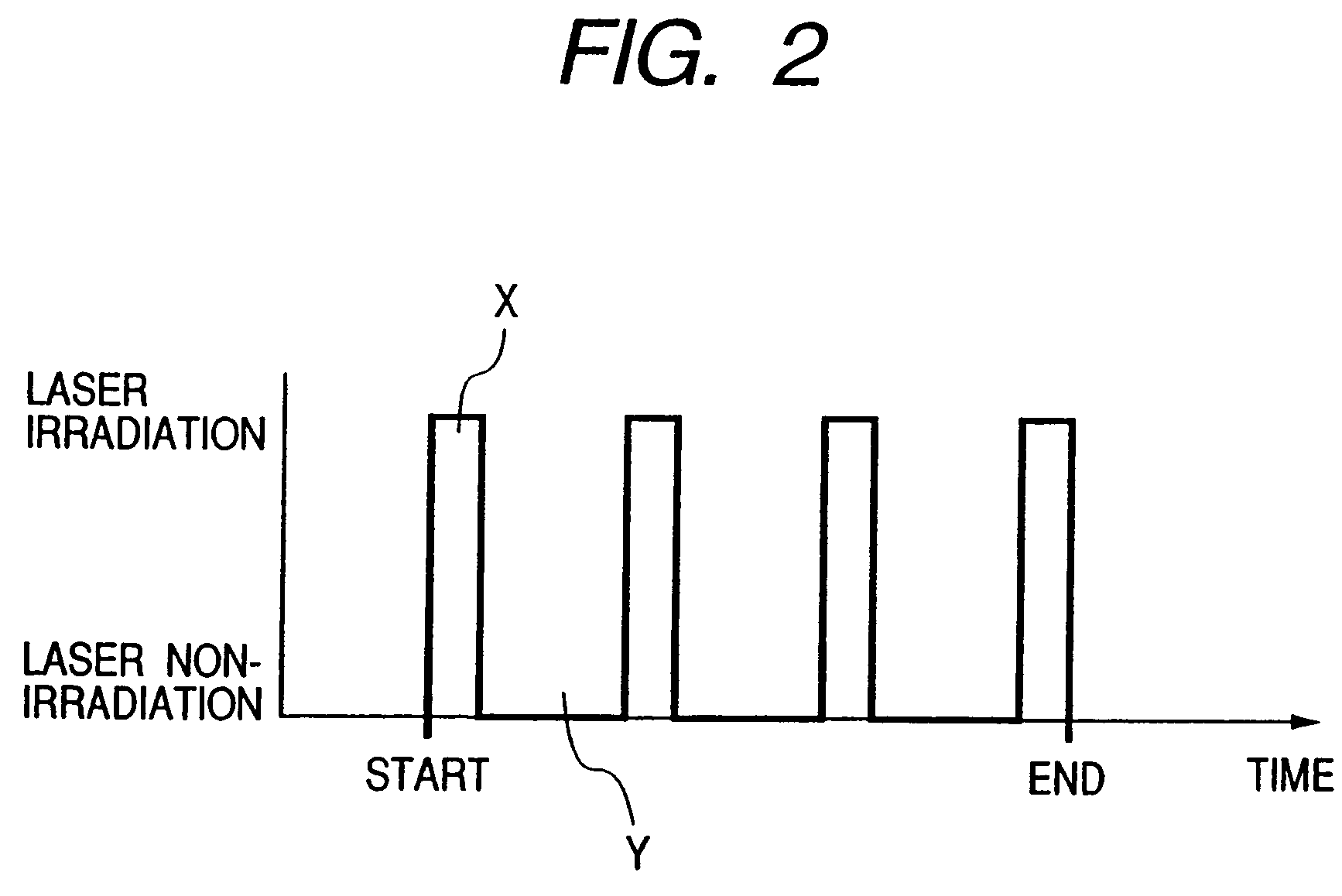
[0072]The laser light 1 is irradiated in pulses in such state to effect sublimation ablation working of the work article 2, and, in the present embodiment, the laser light irradiation is controlled by the open / close control of the mechanical shutter 4-1 to etch the work article 2 in an intermittent sequence.

[0073]In the working method of the present embodimen...

embodiment 2

[Embodiment 2]

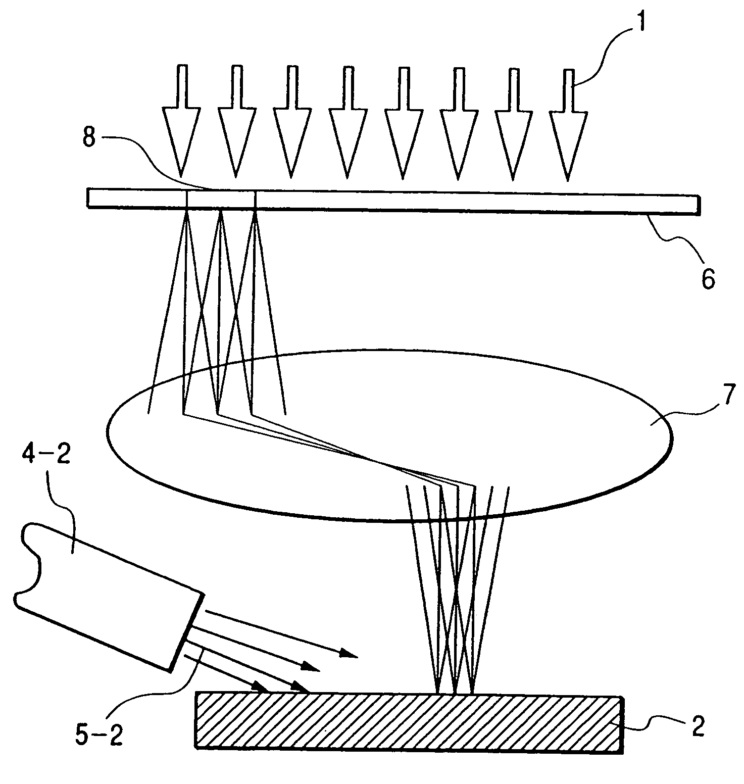
[0077]Now reference is made to FIG. 2 for outlining the working method of the present embodiment. A laser light 1, emitted from an unrepresented laser oscillator, capable of emitting the laser light with an extremely short pulse emission time (not exceeding 1 picosecond), illuminates a photomask 6, and the light transmitted by a mask pattern 8 is projected and focused through a projection lens 7. The projected image is focused on the surface of a work article 2 formed of an inorganic material.

[0078]On the other hand, a gas nozzle 4-2 emits nitrogen gas 5-2 in a direction indicated by an arrow whereby a gas flow is generated on the surface of the work article 2. The laser light 1 is irradiated in pulses to effect sublimation ablation working of the work article 2.

[0079]In the working method of the present embodiment, the continuous etching was executed, by employing a laser light of a wavelength of 775 nm, a laser pulse oscillation frequency of 1 kHz, a laser irradiatio...

embodiment 3

[Embodiment 3]

[0081]Now reference is made to FIG. 6 for outlining the working method of the present embodiment. A laser light 1, emitted from an unrepresented laser oscillator, capable of emitting the laser light with an extremely short pulse emission time (not exceeding 1 picosecond), illuminates a photomask 6, and the light transmitted by a mask pattern 8 is projected and focused through a projection lens 7. The projected image is focused on the surface of a work article 2 formed of an inorganic material.

[0082]The work article 2 is closed in a chamber 3 and a window 4-3 closing the chamber 3 and the space around the work article 2 is filled with a work article atmosphere material 5-3. In such state, the laser light 1 is irradiated in pulses to execute sublimation ablation etching of the work article 2.

[0083]In the working method of the present embodiment, the work article 2 was composed of crystalline silicon, and the chamber 3 was filled with helium gas of normal pressure as the ...


PUM


Abstract

The invention provides a laser etching method for optical ablation working by irradiating a work article formed of an inorganic material with a laser light from a laser oscillator capable of emitting in succession light pulses of a large energy density in space and time with a pulse radiation time not exceeding 1 picosecond, wherein, in laser etching of the work article formed of the inorganic material by irradiation thereof with the laser light from the laser oscillator with a predetermined pattern and with a predetermined energy density, there is utilized means for preventing deposition of a work by-product around the etching position.

Description

[0001]This application is a division of U.S. application Ser. No. 09 / 717,242 filed on Nov. 22, 2000, now U.S. Pat. No. 6,861,364.BACKGROUND OF THE INVENTION[0002]1. Field of the Invention[0003]The present invention relates to a laser etching method and a laser etching apparatus for working an article with a laser beam, and more particularly to a laser etching method and a laser etching apparatus capable, in working the article of an inorganic substance, of working without generating deposition around the etching position, and adapted for fine working of a material for a micromachine, an IC or a diode device.[0004]2. Related Background Art[0005]In fine working of a structural member by laser working, it is customary to utilize a harmonic wave of an excimer laser or a YAG laser.[0006]However, as the energy density of the laser light in the oscillated pulse is limited to a level of 100 megawatts at maximum, such laser working method is hardly applicable to an article formed of an inorg...

Claims


Application Information

Patent Timeline
Patent Type & Authority Patents(United States)
IPC IPC(8): H01L21/302B41J2/455B23K26/06B23K26/16
CPCB23K26/0635B23K26/4075B23K26/365B23K26/16B23K26/40B23K26/0624B23K26/361B23K2103/50B41J2/455
Inventor KOIDE, JUN
Owner CANON KK
Why Eureka
Try Eureka