Scanning probe microscopy cantilever holder and scanning probe microscope using the cantilever holder

a scanning probe and microscope technology, applied in the direction of mechanical measuring arrangements, mechanical roughness/irregularity measurements, instruments, etc., can solve the problems of reducing performance such as measurement accuracy, hammering vibration, change in vibration amplitude or phase, etc., to achieve greater displacement, reduce noise in the vibration of the cantilever, increase the amplitude of the cantilever

Inactive Publication Date: 2007-01-30
HITACHI HIGH TECH SCI CORP
View PDF1 Cites 14 Cited by
  • Summary
  • Abstract
  • Description
  • Claims
  • Application Information

AI Technical Summary

Benefits of technology

[0016]An increased vibrator in size grows weight to cause the reduction in the stiffness of the instrument, vibration proof against the external vibration is decreased, and measurement accuracy is dropped. An increased weight drops the resonance frequency of the instrument to reduce the response when the cantilever and the sample are relatively moved. Consequently, a problem of prolonged measuring time arises.
[0017]Accordingly, an object of the invention is to provide a cantilever holder which can stably vibrate a cantilever by a small-sized vibrator configurable in a limited space even when viscous drag exists.
[0043]In these structures, when the vibrator in the same size is used, it can vibrate with a greater displacement than in the case where the entire fixing part is vertically moved in translation movement. Therefore, the amplitude of the cantilever can be increased.
[0044]Consequently, noise in the cantilever vibration are relatively decreased even under the influence of a solution and atmospheric viscous drag, stable amplitude is obtained that is necessary for measurement, and highly accurate measurement is allowed.
[0045]Besides, when the amplitude is the same, the vibrator is decreased in size to be configured in the limited space. The light-weight apparatus improves the stiffness of the apparatus, and thus measurement accuracy can be enhanced.

Problems solved by technology

They hamper the vibration of the cantilever as viscous drag to cause a change in the vibration amplitude or phase of the cantilever.
A change in the vibrating state caused by viscous drag is unnecessary, leading to a factor that reduces performance such as measurement accuracy.
Particularly, viscous drag is great in the solution, and the vibration is significantly attenuated to increase the ratio of noise components in the vibration of the cantilever, causing a problem that stable amplitude required for sample measurement cannot be obtained.
However, a displacement measuring module is disposed around the vibrator, which measures the amplitude or phase of the cantilever by the optical lever mode, and space is limited to impose limitation on the vibrator for size increase.
Consequently, a problem of prolonged measuring time arises.

Method used


Image

  • Scanning probe microscopy cantilever holder and scanning probe microscope using the cantilever holder
  • Scanning probe microscopy cantilever holder and scanning probe microscope using the cantilever holder
  • Scanning probe microscopy cantilever holder and scanning probe microscope using the cantilever holder

Examples


embodiments

[0057

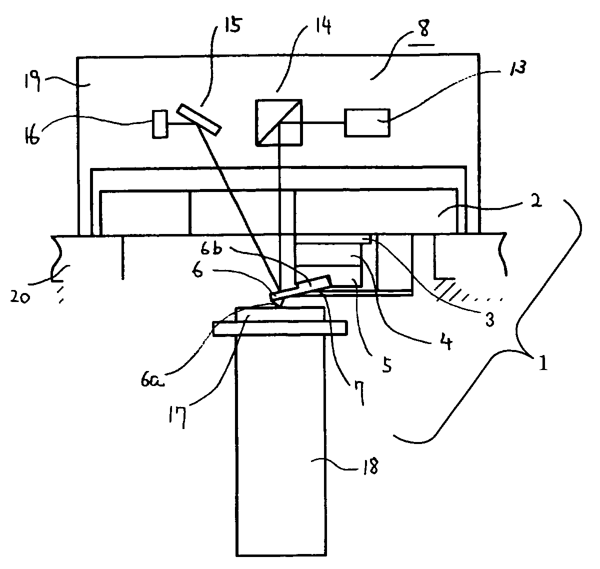
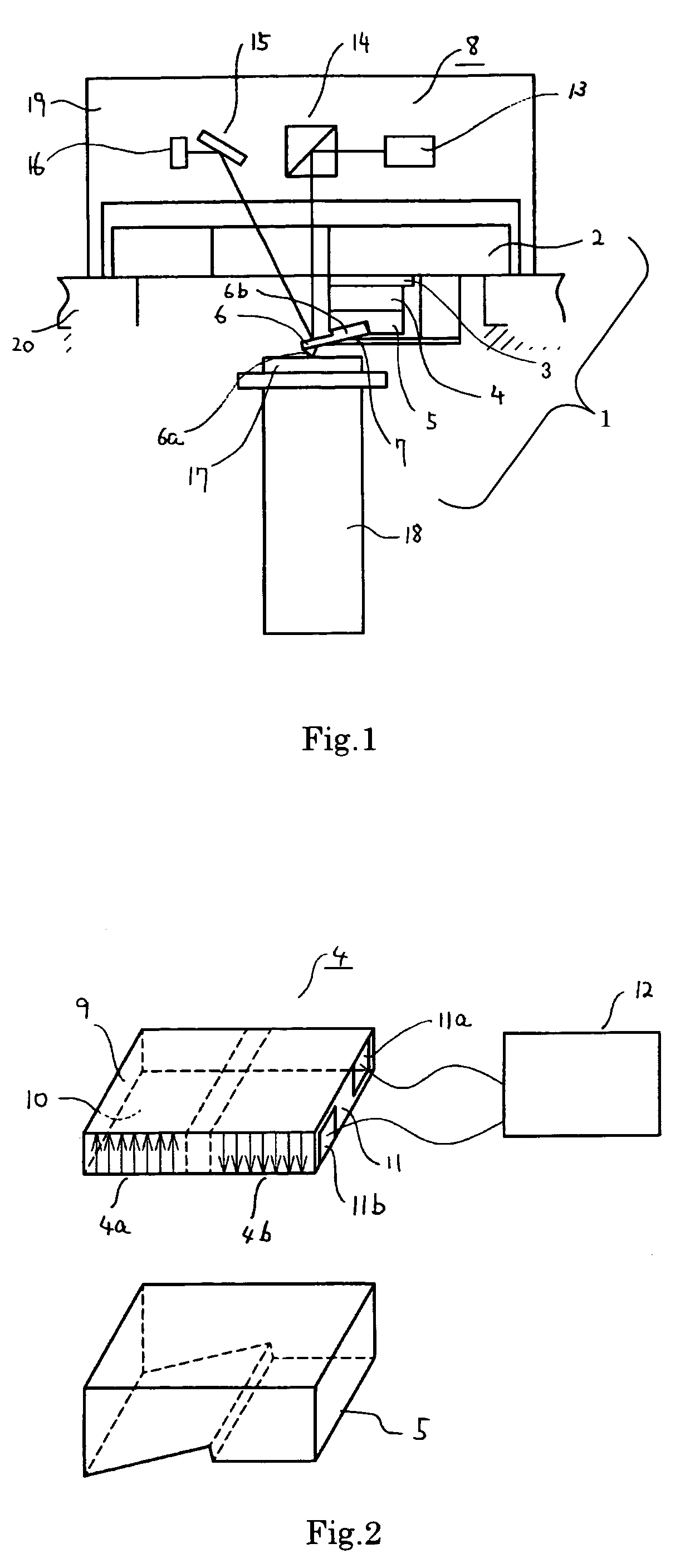
[0058]A first embodiment of a cantilever holder for use in a scanning probe microscope under an atmospheric environment and a scanning probe microscope using the cantilever holder according to the invention is shown in FIG. 1 as a block diagram. To a base block 2 of a cantilever holder 1, a vibrator 4 configured of a piezoelectric device is adhered and fixed through an insulating plate 3. To the vibrator 4, a cantilever fixing part 5 which fixes a cantilever 6 is adhered and fixed. A tilt on which the cantilever 6 is obliquely mounted is formed in the cantilever fixing part 5 in order to reflect the laser beam of an optical lever system 8 for displacement detection.

[0059]On the cantilever fixing part 5, the cantilever 6 is placed which has a microprobe 6a at the top of the cantilever and a base part 6b at the end of the cantilever and is formed of materials such as silicon and silicon nitride. The cantilever 6 is fixed by pressing the base part 6b against the fixing part 5 with...

third embodiment

[0079]FIG. 5 depicts a third embodiment according to the invention. The embodiment is a scanning probe microscope operated in a solution. In addition, the components having the same configuration as those in FIG. 1 are designated the same numerals and signs, omitting the detailed description on the same components.

[0080]A base block 32 in the embodiment has the structure formed of a metal base block 33 and a glass base block 34. To the glass base block 34, a vibrator and a fixing part of the same configuration as those in FIG. 1 are adhered and fixed. Since the vibrator is used in the solution, the periphery is made watertight with a silicon sealing material to prevent an electrical short circuit.

[0081]On the glass base block 34, a projecting part 35 is disposed which has the projection top machined in a flat surface. On the other hand, a Petri dish 36 is placed on a triaxial fine adjustment mechanism 18 configured of a cylindrical piezoelectric device. A sample 37 is fixed in the P...

fourth embodiment

[0086]FIG. 6 depicts a fourth embodiment according to the invention. In the invention, the embodiment is shown that a scanning near-field optical microscope, which is one type of scanning probe microscope, is operated in a solution.

[0087]In a probe 39 according to the invention, the tip end of an optical fiber is sharpened, the top of the probe part is curved against the optical axis of the fiber, an aperture of about 50 nm is disposed at the apex of the probe, a coating layer of chromium is applied for a primary coating, and a coating layer of gold for the surface other than the aperture is formed. Furthermore, on the backside of the probe 39, a mirror surface 40 is disposed for an optical lever system.

[0088]A cantilever holder in the embodiment has the configuration in which a vibrator 44 is fixed to a base block 42 through an insulating plate 43. The vibrator 44 has the same configuration as that shown in FIG. 2. In the embodiment, no cantilever fixing part is disposed. The vibra...


PUM

PropertyMeasurementUnit
distanceaaaaaaaaaa
scanning probe microscopyaaaaaaaaaa
scanning probe microscopeaaaaaaaaaa

Abstract

A scanning probe microscope having a cantilever holder is provided which gives a cantilever great amplitude by a small-sized vibrator configurable in a limited space and is stably operated even in environments of high viscous drag such as a liquid. A cantilever base part of a cantilever is fixed to a fixing part of a scanning probe microscopy cantilever holder. A vibrator is mounted on the fixing part. When it is defined that the front side is the side close to a probe and the rear side is the side close to a supporting part of the fixing part along in the longitudinal direction of the cantilever, the vibrator displaces the front and rear sides of the fixing part of the cantilever holder to each other in the opposite directions within the plane orthogonal to the sample surface to vibrate the cantilever in a liquid.

Description

BACKGROUND OF THE INVENTION[0001]1. Field of the Invention[0002]The present invention relates to a scanning probe microscopy cantilever holder which vibrates a cantilever having a probe at the top of the cantilever in the direction orthogonal to the surface of a sample and relatively scans the sample and the probe by a fine adjustment mechanism while detecting the interaction between the probe and the surface to control the distance for measuring the topography and physical properties of the sample surface, machining the sample surface, or moving substances on the sample surface by the probe, and to a scanning probe microscope using the cantilever holder.[0003]2. Description of the Related Art[0004]In a traditional scanning probe microscope, the base part at the end of a cantilever having a probe at the tip end thereof is fixed to a cantilever holder, and forcedly vibrated at the frequency near the resonance frequency of the cantilever by a vibrating module such as a piezoelectric d...

Claims


Application Information

Patent Timeline
Patent Type & Authority Patents(United States)
IPC IPC(8): G01N13/16G01B5/28G01Q30/14G01Q60/32G01Q70/02G01Q90/00
CPCB82Y35/00G01Q70/02G01Q60/34
Inventor IYOKI, MASATOSHIGENO, MASATSUGU
Owner HITACHI HIGH TECH SCI CORP
Why Eureka
Try Eureka