Rectangular tilt-up concrete tank construction

a technology of tilt-up concrete and rectangular concrete, which is applied in the field of rectangular tilt-up concrete tank construction, can solve the problems of extreme safety hazards of conventional rectangular concrete tank construction, tripping hazards, and at worst, an instrument for severe injuries to workers, and achieves the effects of reducing the safety hazards associated, eliminating significant environmental deficiency, and convenient liquid tightening and repair

Active Publication Date: 2007-02-06
CH2M HILL
View PDF38 Cites 38 Cited by
  • Summary
  • Abstract
  • Description
  • Claims
  • Application Information

AI Technical Summary

Benefits of technology

[0012]The rectangular tilt-up concrete tank and method for making the same substantially reduces the safety hazards associated with conventional rectangular tank construction. Climbing of reinforcing steel and formwork is substantially eliminated, as is the flying in of materials via overhead cranes. Dangerous, protruding reinforcing at the slab and side panel construction joints is eliminated. Furthermore, the rectangular tilt-up concrete tank of the present invention requires little or no wood formwork. This eliminates a significant environmental deficiency associated with conventional rectangular tank construction. The liquid-tight welded joints of the present invention eliminate conventional construction joints and are relatively easy to make liquid-tight and to repair if leakage testing reveals defects. Many sources of concrete defects are also eliminated. For example, because the wall sections are formed while lying horizontal, they can be readily covered by plastic during curing to improve effective curing. Furthermore, potential defects such as misalignment and concrete consolidation are substantially reduced or eliminated. Finally, the rectangular tilt-up tank and method significantly reduces the intensive labor necessary to erect reinforcing and formwork and then strip the formwork. Most overhead work is also eliminated and numerous time consuming steps such as framing, stripping, water-stop placement, roughing of construction joints and finishing work are reduced or eliminated. Crane time, which is always a large expense on such a project, is also substantially reduced over conventional rectangular concrete tank construction.

Problems solved by technology

First, conventional rectangular concrete tank construction creates extreme safety hazards for construction personnel.
Extending reinforcing steel at best creates a tripping hazard and at worst an instrument for severe injury to workers.
Conventional rectangular concrete tank construction often requires workers to climb reinforcing steel and formwork which are not intended to support construction personnel, creating a risk of falling.
Furthermore, the use of cranes to “fly-in” reinforcing steel, formwork and concrete creates obvious overhead hazards.
Moreover, the piece-meal nature of conventional rectangular concrete tank construction creates a myriad of other specific hazards associated with the necessary carpentry, concrete finishing, and reinforcement placement trades, including formwork clutter, extensive small tool usage, extension cords and cutting tools, to name but a few.
Second, the extensive use of wood formwork in conventional rectangular concrete tank construction also raises environmental issues.
Third, conventional rectangular concrete tank construction techniques inherently create the potential for concrete defects such as misaligned concrete panels and concrete consolidation problems.
Furthermore, water leakage problems associated with shrinkage, cracking, tie holes, water stop installation and the use of construction and expansion joints are commonplace.
Further problems with conventional rectangular concrete tank construction include high labor costs, high material costs and equipment usage costs and sequencing difficulties caused by the need to stagger concrete panel placements to prevent shrinkage cracking.
Furthermore, efficient access to the construction site for workers and equipment is severely hampered by protruding reinforcing dowels.
In addition, stripping formwork at the construction site can be hazardous because of protruding reinforcing.
Moreover, curing of vertical concrete surfaces can be difficult and a substantial amount of finishing work may be required after the concrete has been poured.

Method used


Image

  • Rectangular tilt-up concrete tank construction
  • Rectangular tilt-up concrete tank construction
  • Rectangular tilt-up concrete tank construction

Examples


Embodiment Construction

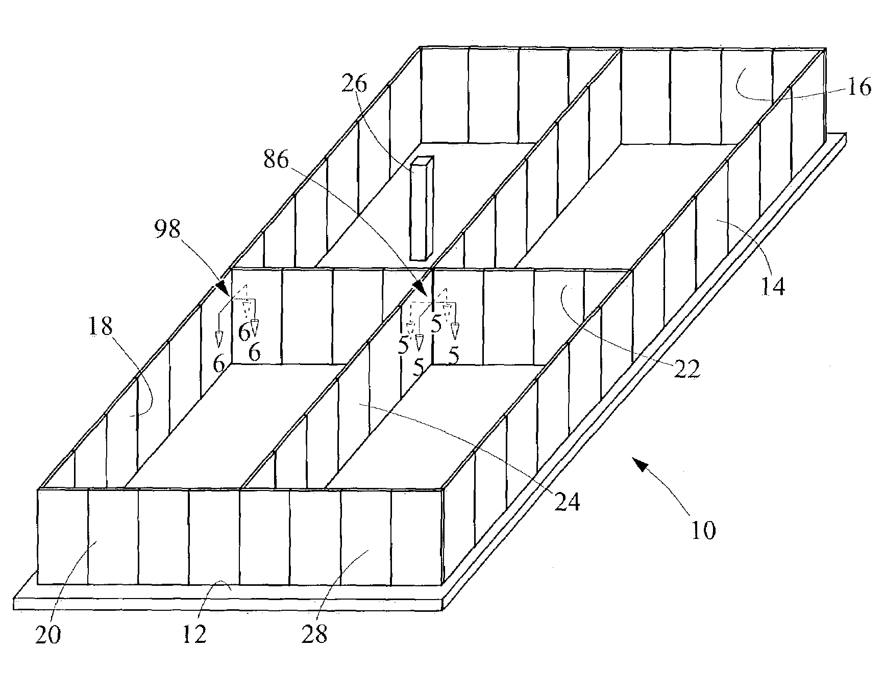
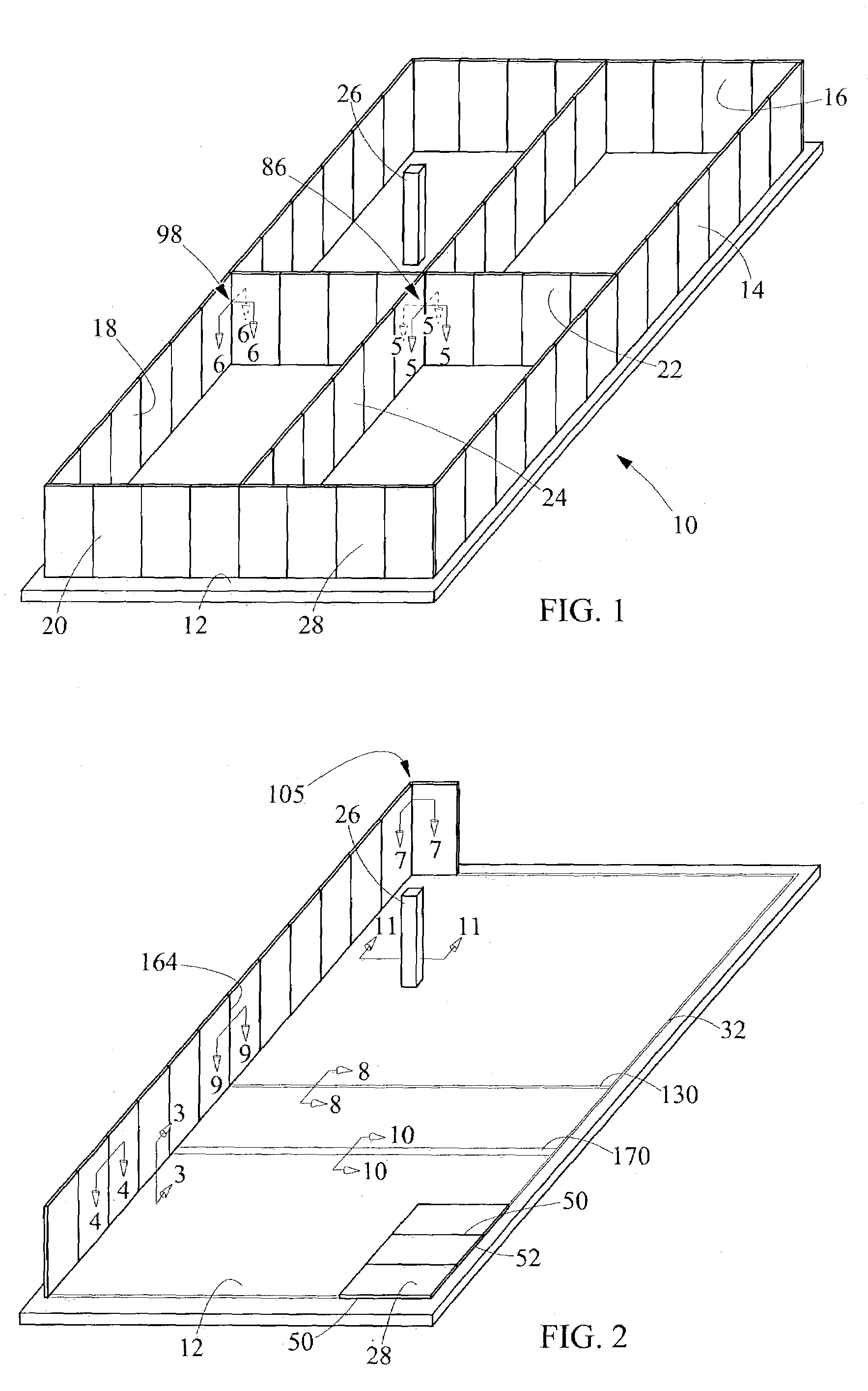
[0027]A rectangular tilt-up concrete tank 10 is shown in a perspective view in FIG. 1. The rectangular tilt-up concrete tank 10 includes a concrete slab 12 and four side walls 14, 16, 18, 20 extending therefrom. Within a volume defined by the rectangular tilt-up concrete tank 10 one or more longitudinal dividing walls 24 and / or one or more transverse dividing walls 22 may be included to form compartments or direct flow. In addition, one or more columns 26 may be included within the tank to support a roof or other ancillary structures, which are not illustrated in FIG. 1 for the sake of clarity. Each of the side walls 14, 16, 18, 20 are made up of a number of preformed concrete side panels 28. At a minimum, the tilt-up concrete tank 10 consists of the bottom slab 12 and side walls 14, 16, 18, 20. The interior walls 22, 24, column 26 or a roof (not shown), as well as other interior structures, such as walkways and ladders, may be included as required by the purpose of the tank. In a m...


PUM


Abstract

A rectangular tilt-up concrete tank includes a concrete slab with a metal plate anchored thereto, the metal plate defining at least one substantially linear concrete side wall location. A plurality of preformed concrete side panels each having metal plates attached along a bottom edge and opposing side edges are welded in a liquid-tight weld to the metal plate defining the concrete side wall location and a side metal plate of each side panel is welded to a metal side plate of an adjacent side panel in a liquid-tight weld to define a concrete side wall. Horizontal and vertical post-tensioning sleeves are provided in the side panels for receiving post-tensioning tendons.

Description

TECHNICAL FIELD[0001]The present invention relates to tank construction, and more particularly to a rectangular tilt-up concrete tank construction.BACKGROUND ART[0002]Conventional rectangular concrete tank construction makes extensive use of wood formwork to define vertical walls and steel reinforcing bars which extend from slabs and adjacent walls to facilitate the joining of walls to the slab or adjacent walls to each other. The use of conventional rectangular concrete tank construction has many drawbacks. First, conventional rectangular concrete tank construction creates extreme safety hazards for construction personnel. Extending reinforcing steel at best creates a tripping hazard and at worst an instrument for severe injury to workers. Conventional rectangular concrete tank construction often requires workers to climb reinforcing steel and formwork which are not intended to support construction personnel, creating a risk of falling. Furthermore, the use of cranes to “fly-in” re...

Claims


Application Information

Patent Timeline
Patent Type & Authority Patents(United States)
IPC IPC(8): E04H3/00E02D27/38E04B1/06E04B1/343E04H4/00E04H7/20
CPCE04H7/20E04H4/0087
Inventor THOMASON, DAVIDGOODSON, MARY WILLIAMSSUNDBERG, CHRISTIAN CARLDOLEAC, MICHAEL LOUIS
Owner CH2M HILL
Why Eureka
Try Eureka